

What Lab Accuracy Specs Hide About 3D Scanning Castings
What Lab Accuracy Specs Hide About 3D Scanning Castings. Quality teams that invest in 3D scanning castings often start with a spreadsheet.
The scan data from a production casting — with draft angles, mold lines, and a surface finish that hasn’t been uniformly shot-blasted — tells a different story entirely. That gap between brochure numbers and floor-level capability is what derails many casting inspection investments.
The assumption rarely stated out loud
Lab accuracy is a reliable proxy for shop-floor performance. That’s the quiet assumption. Teams shortlist systems based on those numbers, skip the step of running a validation study with the actual castings they inspect every day, and then wonder why their dimensional reports don’t hold up during an audit.
Deployment Validation Checklist
| Focus Area | Decision Point | Deployment Note |
|---|---|---|
| Target part | Check size, surface condition, and key tolerances against the scan task | Run a full trial scan on a representative part |
| Data workflow | Verify point cloud, deviation map, and quality-report handoff | Confirm export formats and review ownership in advance |
| Shop-floor use | Review training, calibration, lighting, and working space | Keep the validation record as a repeatable inspection reference |
What gets missed is a simple reality: 3D scanning as-cast parts demands repeatability on textured surfaces, stability across a range of ambient conditions, and enough data density to capture blend radii, wall thickness transitions, and the subtle warpage that happens during cooling — not just the nominal geometry of a machined artifact.
Scenario Snapshot
A practical way to read the article is through this scenario:
- The assumption rarely stated out loud: Lab accuracy is a reliable proxy for shop-floor performance.
- What matters more than the spec sheet: Foundries and machining OEMs are shifting from hard gauges and CMM spot checks to full-field 3D scanning for casti…
- Defining the boundaries where the system works: The most reliable path to an ROI-positive 3D scanning investment starts with an uncomfortable truth: no single sca…
Aerospace and energy supply chains are squeezing first-article inspection timelines for cast components. More teams are turning to 3D scanning castings to replace slow CMM routines, only to hit a familiar wall. The published specs never match what they see on the floor. Lab measurements use polished, calibrated artifacts under perfectly controlled conditions. Those conditions bear no resemblance to a working foundry.
Rough castings hold sand residue, shot-blast texture, and partially machined features. Deep bores, undercuts, and internal cooling channels — common in aerospace castings — create gaps in data continuity. Large, heavy assemblies that are too cumbersome to reposition introduce further challenges. Add in ambient press vibration, temperature swings, and uneven overhead lighting, and the readings skew.
The result for quality leads is predictable: rejected inspection reports, repeated re-scans, and non-compliant audit trails that disrupt delivery schedules.

What matters more than the spec sheet
Foundries and machining OEMs are shifting from hard gauges and CMM spot checks to full-field 3D scanning for casting inspection. A spec sheet alone won’t tell you whether a system will hold up on the shop floor. Quality teams are better served by a structured field validation framework that tests systems against their own as-cast, shot-blasted, and machined production parts — not lab calibration artifacts.
Four metrics deserve priority. The first is surface adaptability: can the scanner capture consistent data across the full range of surface finishes without spraying, etching, or other prep that slows throughput? The second is geometric coverage: can it reach into deep pockets, thin walls, and internal features that define the casting’s function?
The third is environmental stability: will the system hold calibration and deliver repeatable results when the ambient temperature shifts by 10°C between morning and afternoon? The fourth is data density and edge definition: can it resolve the blend radii and parting line flash that affect assembly fit, without the point cloud thinning out on dark or slightly reflective surfaces?
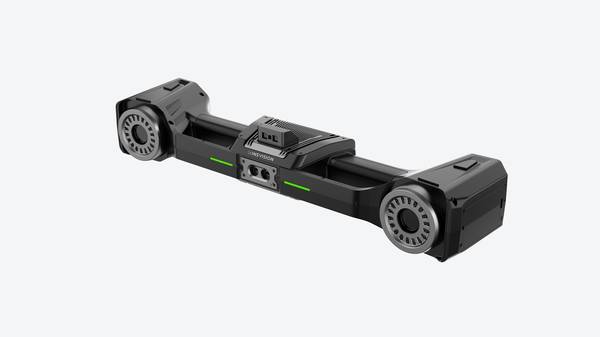
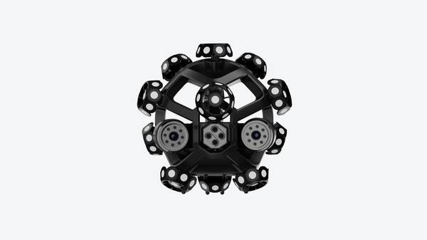
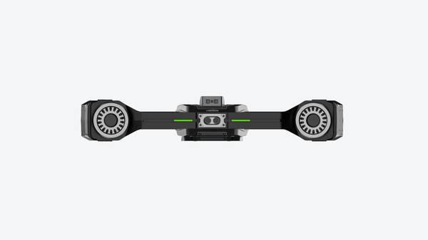
A common misconception in casting inspection is that laser scanning systems cannot reliably capture dark, textured, or slightly reflective as-cast surfaces without heavy surface preparation. The INSVISION V-Track tracking 3D scanning system is designed specifically to counter that assumption.
Its optical architecture and high-dynamic-range detection consistently deliver high point density on raw castings — from sand-cast iron to investment-cast aluminum — without developer sprays. This eliminates the data gaps and prep time that inflate inspection costs and slow first-article throughput.
The system’s large-volume tracking capability and portability mean it can scan a one-ton pump housing in the foundry cell or a tray of smaller investment castings at the incoming inspection bench, without requiring a dedicated metrology lab.
Defining the boundaries where the system works
The most reliable path to an ROI-positive 3D scanning investment starts with an uncomfortable truth: no single scanner fits every casting workflow. Quality leads who treat published lab specs as a guarantee of shop-floor performance routinely end up with a system that underdelivers where it matters most.
The INSVISION V-Track system proves its value in clearly bounded use cases: first-article inspection of medium to large castings, at-line or in-cell inspection within foundry and machining cells, reverse engineering of legacy casting tooling, and incoming quality inspection for cast component suppliers.
These are the applications where its large-volume tracking, portability, and ability to handle darker surface finishes without excessive preparation align with real production demands.
Even within these boundaries, the casting inspection solution fit must be verified with your own parts, your own surface conditions, and your own throughput targets. On-site validation with a sample set that represents your worst-case geometry, minimal surface prep, and actual GD&T callouts is the only way to confirm the boundary conditions. Leaving that step out replaces engineering judgment with hope.
The takeaway for quality teams is straightforward: prioritize use-case-specific validation over specification sheets. That approach keeps the scanning investment aligned with both quality compliance requirements and lean manufacturing goals — no generic claims, no surprises.
In practice, a validation study for a typical valve body casting might involve scanning a set of parts across the morning shift, with the foundry bay doors open, collecting data on the same datum features that the CMM checks. The deviation maps and GD&T reports generated from the scan data are compared directly to the CMM results.
The goal is not to find a perfect match under ideal conditions, but to understand the repeatability envelope under real working conditions. When the data shows consistent agreement on critical-to-function features, the quality team can then move forward with confidence. That confidence comes from a process built on field evidence, not from a number circled on a brochure.
Hangzhou Insvision Technology Co., Ltd.
Address: Building 1, No. 1399 Liangmu Road, Yuhang District, Hangzhou, Zhejiang 311121, China
Copyright © Hangzhou Insvision Technology Co., Ltd. All rights reserved.
Copyright © Hangzhou Insvision Technology Co., Ltd. All rights reserved.