

3D Scanner Tracking Visibility: What to Verify Before Equipment Selection
3d scanner tracking visibility: check line of sight, occlusions, and scanner orientation on a representative part before selecting tracked scanning equipment.
Understanding the 3D scanning question
Tracking visibility planning concerns workpieces where the line of sight between the tracker and scanner can change during capture. The technical purpose is to maintain a usable tracking relationship while the scanner moves around the part and while occlusions appear from geometry, fixturing, or operator position.
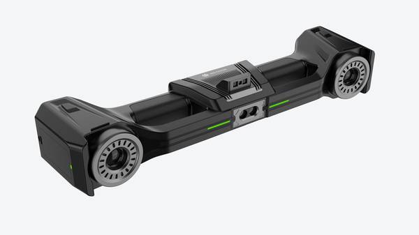
The usable output is a scan sequence in which each captured frame remains connected to the tracked coordinate system. The observable information includes where tracking remained stable, where visibility was interrupted, and how scanner orientation and tracker position supported continuous frame acquisition across the workpiece.
Deployment Validation Checklist
| Focus Area | Decision Point | Deployment Note |
|---|---|---|
| Target part | Check size, surface condition, and key tolerances against the scan task | Run a full trial scan on a representative part |
| Data workflow | Verify point cloud, deviation map, and quality-report handoff | Confirm export formats and review ownership in advance |
| Shop-floor use | Review training, calibration, lighting, and working space | Keep the validation record as a repeatable inspection reference |
What to check on a representative part
On a representative workpiece, confirm that the scanner maintains a tracked state while moving across areas that partially block the direct path to the tracker. Check whether the displayed tracking condition remains usable when the scanner is rotated into several working orientations.
Introduce a temporary occlusion and observe whether the system reports a loss of tracking. Verify that after the occlusion is removed, the scanner can resume capture without a new coordinate setup. Leave unresolved whether every possible occlusion on the current part will behave the same way.
What the official material establishes
The official V-Track user manual establishes that the product is a tracked laser 3D scanner and documents scan preparation and frame-point scanning. This supports the existence of a tracked scanning workflow in which frame capture depends on a maintained tracking relationship.
The official material does not establish a result or acceptance decision for the current part. It does not specify which occlusions will interrupt tracking on a particular workpiece or how every scanner orientation will perform during a given scan sequence.
FAQ
What does tracking visibility cover?
Tracking visibility covers the changing line of sight between the tracker and scanner while capturing a workpiece. Readers should compare how different scanner orientations and occlusions affect the ability to keep frames connected to the tracked coordinate system.
What should be checked on a representative part?
A representative part should be checked by moving the scanner through partially blocked areas and rotating it into different working orientations. A temporary occlusion can show whether tracking is lost and whether capture resumes after the line of sight returns.
What does official V-Track material state?
The official V-Track user manual identifies the product as a tracked laser 3D scanner and documents scan preparation and frame-point scanning. This confirms that the product supports a tracked scanning workflow but does not state how every occlusion will affect a specific workpiece.
Hangzhou Insvision Technology Co., Ltd.
Address: Building 1, No. 1399 Liangmu Road, Yuhang District, Hangzhou, Zhejiang 311121, China
Copyright © Hangzhou Insvision Technology Co., Ltd. All rights reserved.
Copyright © Hangzhou Insvision Technology Co., Ltd. All rights reserved.