

Complex Inspection Costs Rise When a 3D Scanner Laser Setup Misses Production Constraints
3d scanner laser: Meta description: Factory leaders keep losing inspection time to rescans, poor alignment, and data that arrives after line decisions.
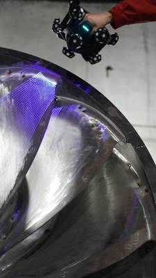
Dimensional inspection in North American and European plants has moved from a delayed QC gate into the production line. Automotive stamping groups, aerospace MRO teams, medical device suppliers, and energy component manufacturers now expect a 3D scanner laser to verify tooling, support first-article approval, and flag surface deviation without stopping the line. The business problem is rarely the scanner’s published accuracy.
It is the mismatch between the measurement setup and the part geometry, surface finish, shop-floor access, and delivery cadence. When that mismatch is ignored, costs reappear as rescans, alignment corrections, manual CAD cleanup, and delayed customer submissions.
That is the angle this article takes: inspection as an operating cost driver, not a technology demonstration.
Where Inspection Costs Accumulate Before a 3D Scanner Laser Is Selected
In many factories, dimensional verification still depends on a bridge CMM in a metrology lab, modular fixturing, and a skilled programmer. The part moves offline. The setup is reprogrammed for the next variant. The measurement report may arrive after the machining cell has already made the next batch. For a 3D scanner laser to improve that flow, it must handle the same part constraints where the part actually sits.
Common cost points include:
- Rework caused by wrong rejection: A dense point cloud can show a part out of tolerance because multi-scan registration drifted. The same part may pass on a CMM. Engineering time goes into proving the scan wrong, not solving a part problem.
- Missing coverage on critical features: Deep bores, undercuts, rib roots, and flange intersections often create sparse data. The problem appears after the part has moved downstream, forcing another setup and another scan.
- Reflective surfaces and variable plant lighting: These create noise that QA teams must isolate from true form deviation. That sorting work is non-value-added labor.
- Audit risk from weak datum traceability: A scan can be complete and still create audit exposure if it is not tied to the drawing datum reference frame. Later, engineers reconstruct alignment history to defend a submission.
These are not metrology failures as much as workflow selection failures. The equipment may be capable, but the configuration was not matched to the part and the production environment.
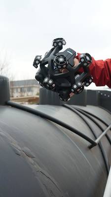
How a Production-Matched 3D Scanner Laser Changes the Cost Path
A cost reduction argument for a 3D scanner laser should focus on four or five specific operating loops.
First-Article Inspection and Tooling Buyoff
First-article delays are expensive because they hold supplier approval, customer submission cycles, and internal release decisions. A production-matched scanning workflow can capture critical GD&T callouts on the part, in place, with alignment tied to the drawing datums. The improvement is not simply faster point capture; it is fewer downstream arguments about whether the scan reflects the part.
That translates into shorter approval cycles and fewer repeat submissions.
In-Process Verification and Rework Control
When scanning occurs at the cell or in a nearby inspection zone, the plant can identify form and position issues before additional value is added. A 3D scanner laser setup that keeps a stable coordinate reference across a large part, such as a housing or welded structure, reduces the probability of alignment drift and sparse data.
The observable value is less rework, fewer stopped batches, and less waiting for the metrology lab.
Skilled Labor and Programmer Bottlenecks
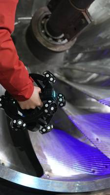
CMM programming and fixture setup often concentrate in one or two specialists. If inspection data can be captured with a defined scanning procedure and validated against pass/fail callouts, more routine measurement work can move to production technicians. The goal is not to replace skilled staff but to avoid letting every critical inspection wait on that bottleneck.
Quality Traceability and Customer Confidence
Western aerospace, automotive, and medical customers increasingly expect measurement data to be traceable to part datums. If a 3D scanner laser workflow records alignment at capture, not as a post-processing repair, audits become easier to answer. That reduces the hidden cost of defending non-conformance claims and improves supplier standing.
A Practical Cost-Evaluation Framework for a 3D Scanner Laser
Plant managers often ask for a simple payback calculation. The credible version does not require elevated ROI claims; it requires the plant to measure five cost drivers before and after a trial.
| Cost driver | What to record before implementation | What to evaluate with a 3D scanner laser |
|---|---|---|
| Measurement cycle time | Time from part removal or setup to first report | Time from scan start to first report in the production cell |
| Rework and rescans | Number of repeated inspections or scan attempts per part | Number of rescans or missing coverage zones per part |
| Skilled labor load | Hours spent on CMM programming, fixture setup, and alignment | Hours spent on scan execution and report validation |
| Delivery cadence | First-article approval delays and customer submission timing | Reduction in approval wait time and report availability |
| Audit defense cost | Engineering time to reconstruct alignment or recheck data | Availability of datum-aligned capture and repeatability evidence |
This framework lets a company test a 3D scanner laser against the constraints that already affect orders, scrap, and delivery. The right evaluation is not a long feature list. It is two or three pass/fail criteria tied to parts that currently stop shipment.
Where INSVISION V-Track Fits the Cost Conversation
INSVISION approaches in-factory inspection by defining capture, alignment, rescan, and validation requirements before hardware selection. That matters because one of the most expensive failure modes is a high-density scanner that still drifts during multi-scan stitching on a large part.
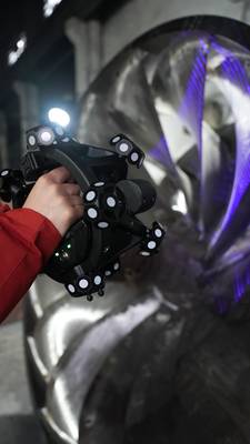
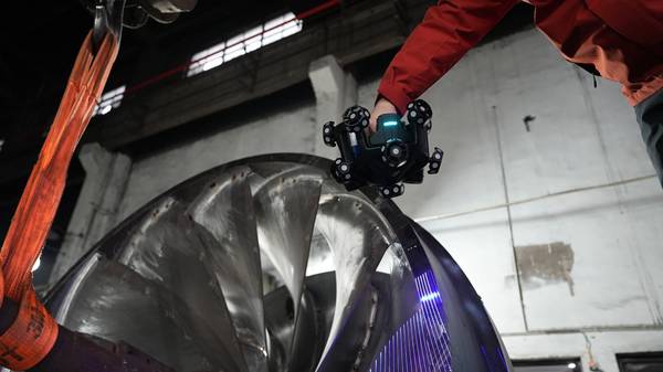
The INSVISION V-Track tracking 3D scanning system is designed for medium-to-large industrial components that cannot easily move to a metrology lab. The tracking unit maintains a stable reference while the 3D scanner laser moves across the part. That keeps alignment more consistent across long scan sequences, reduces patchy coverage, and cuts the reset-and-rescan loop that drains labor hours.
Because the workflow ties alignment to part datums during capture, inspection data is closer to audit-ready than a typical scanner-and-postprocess path.
The operational fit is strongest for tooling verification, first-article inspection, and in-process quality checks on automotive, aerospace, medical device, or energy components. If the plant needs ultra-portable scanning for remote field sites or fully inline high-speed automated inspection, a different solution category may be more appropriate. The useful test is not accuracy alone;
it is whether the part stays in the factory, whether features are distributed across a larger envelope, and whether data must arrive in time to inform the next machining or assembly decision.
Implementation Sequence That Protects the Investment
Managers do not need to replace every gage or CMM at once. A staged approach reduces risk and builds internal evidence.
- Choose two or three critical part types. Pick parts that currently cause repeated first-article rework, audit questions, or line-side delays. Write down two or three GD&T callouts that actually control shipment decisions.
- Run a production-environment trial. Test in the real cell with the same vibration, lighting, and fixture access. Lab demonstrations hide the rework drivers that matter.
- Compare repeatability. Run three consecutive full-part scans and examine alignment consistency. If scan-to-scan repeatability is unstable, downstream reports will be difficult to defend.
- Time the full workflow. Measure from scan start to the first usable inspection report, including any CAD or QMS export steps. Compare that against the production takt time or first-article deadline.
- Move to routine use only after the evidence supports it. If the selected 3D scanner laser setup clears the pass/fail criteria, expand to tooling verification or in-process checks before broader deployment.
This sequence turns a purchase decision into an operational pilot. It gives cost accountants and plant managers something more credible than a vendor presentation: data from their own floor.
Summary
A 3D scanner laser only improves manufacturing economics when the setup matches the part, the production environment, and the inspection workflow. The hidden costs of standard configurations—alignment drift, missing data on deep features, reflective-surface noise, and weak datum traceability—show up as rescans, additional labor, delayed approvals, and audit exposure.
A more useful evaluation focuses on measurement cycle time, rework loops, skilled labor bottlenecks, delivery cadence, and documentation quality.
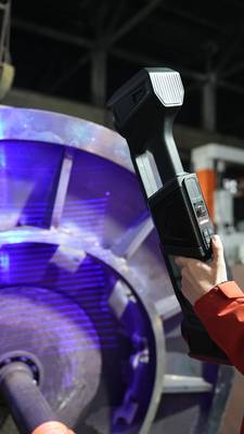
INSVISION’s V-Track tracking 3D scanning system targets those cost drivers by maintaining a stable reference during capture and tying alignment to the drawing datum frame. For plants whose parts remain in the factory and whose inspection data must support real-time production decisions, that is a practical fit. The first move is not to buy more point density.
It is to define the two or three constraints that currently stop shipments and run a trial against them.
Hangzhou Insvision Technology Co., Ltd.
Address: Building 1, No. 1399 Liangmu Road, Yuhang District, Hangzhou, Zhejiang 311121, China
Copyright © Hangzhou Insvision Technology Co., Ltd. All rights reserved.
Copyright © Hangzhou Insvision Technology Co., Ltd. All rights reserved.