
3D coordinate measuring machine: Practical Criteria for Manufacturing Te
A technical deep-dive into how a wireless optical tracking 3D coordinate measuring machine works, its accuracy, and how INSVISION X-Track delivers shop-floor results.
Walk through any large fabrication bay or heavy machining cell and you’ll see the same tension: parts are getting bigger, tolerances tighter, and the granite-table CMM is still bolted to the floor three buildings away. That mismatch has pushed optical tracking 3D coordinate measuring machines from a niche curiosity into a mainstream industrial tool.
Yet plenty of engineers still wonder whether a wireless, camera-based system can really hold its own against a fixed gantry—and if so, where the boundaries actually lie.
This article explains what wireless optical tracking 3D CMMs are, how they maintain accuracy without a rigid structure, where they fit (and where they don’t), and what separates a practical shop-floor system from a lab-only demonstrator.
Along the way, we’ll look at how INSVISION’s X-Track architecture addresses the real-world physics of vibration, ambient light, and thermal drift that kill measurement confidence outside a metrology lab.
What a Wireless 3D Coordinate Measuring Machine Actually Is
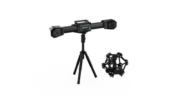
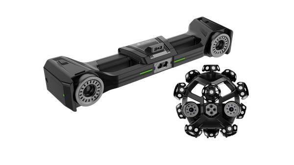
A conventional coordinate measuring machine relies on a physical reference frame: a granite base, precision guideways, and linear scales that define a Cartesian volume. A wireless optical tracking 3D CMM replaces that rigid structure with a dynamic coordinate system defined by infrared LEDs or passive markers mounted on a handheld probe.
An array of stereo cameras in a separate optical tracker continuously triangulates the position of those markers in 3D space, establishing a live spatial reference frame that moves with the part and the tracker.
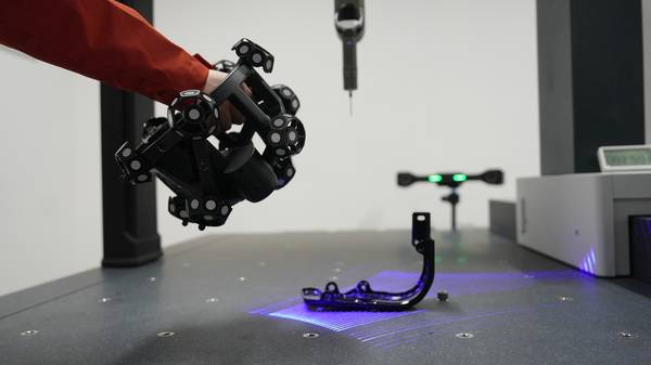
As the operator moves the probe, the system performs real-time pose estimation—calculating the probe’s exact location and orientation relative to the part hundreds of times per second. Because the coordinate system isn’t tied to a fixed machine bed, the measurement remains valid even if the workpiece shifts slightly during inspection.
There’s no cable drag, no physical rails, and no need to fixture a 12-ton assembly on a granite table.
The output is a dense point cloud, not a sparse set of discrete probed points. That full-surface data supports GD&T evaluations per ASME Y14.5, deviation color maps, and CAD alignment without the sampling risk inherent in touch-trigger methods.
Accuracy without a climate-controlled room
Optical tracking systems don’t escape physics—they manage it differently. Vibration, thermal expansion, and airborne dust all degrade point cloud quality if left unfiltered. INSVISION embeds proprietary AI-driven 3D reconstruction algorithms directly into the measurement pipeline to suppress environmental noise. The result is metrology-grade data that holds tight tolerances on a live production floor, not just in a lab.
Factory-calibrated optical sensors ship with a traceable certificate, eliminating field calibration and the operator-to-operator variation that comes with it.
Wireless architecture and data integrity
Cable drag is a subtle but persistent source of bias in articulated arm CMMs. A wireless probe removes that variable entirely. INSVISION’s X-Track uses a dedicated radio link—not standard Wi-Fi—to maintain low latency and resist electromagnetic interference on active shop floors. The data stream stays clean even when the operator walks around a large casting or climbs onto a fixture.
Software integration and the digital thread
Raw point clouds have limited value without a fast path to actionable dimensional data. X-Track integrates natively with INSVISION’s 3D software and SMARPARA Q, handling GD&T callouts, CAD alignment, and deviation heatmaps without file conversion steps. The AI-powered processing engine automates point cloud segmentation, noise filtering, and reference geometry alignment, cutting first-article inspection time noticeably.
Export options feed directly into existing QMS platforms, so the measurement data becomes part of the part’s digital record—not a disconnected report.
Certifications and traceability
CE, FCC, and CNAS certifications back electromagnetic compatibility, safety, and metrological traceability. For shops operating under ISO 9001 or AS9100, this means the system slots into existing quality workflows without a separate validation project.
How Optical Tracking Compares to Other Industrial Metrology Tools
The choice isn’t about which technology is “better” in the abstract—it’s about which one matches the part size, environment, and data requirements.
| Technology Category | Key Strengths | Ideal Scenarios |
|---|---|---|
| Wireless optical tracking 3D CMM (e.g., INSVISION X-Track) | Full-surface 3D data without contact; portable; works on the shop floor or at large assemblies; handles parts from small precision components to multi-meter structures; high measurement speed with real-time feedback. | On-site inspection of large tooling, jigs, and welded structures; reverse engineering of complex freeform surfaces; alignment and assembly guidance where moving the part is impractical. |
| Fixed gantry CMM | Extremely high volumetric accuracy and repeatability in temperature-controlled environments; well-suited for automated, high-throughput routines; tactile probing delivers reliable results on prismatic features and tight GD&T callouts. | High-volume repeat inspection of small to medium machined parts in a quality lab; first-article inspection where traceable, sub-micron uncertainty is required. |
| Manual handheld tools (calipers, micrometers) | Low cost, simple operation, no programming needed; immediate feedback on basic linear dimensions; robust and usable anywhere. | Quick spot checks of turned diameters, thicknesses, and simple lengths during machining setup or in-process verification; applications where only a few critical dimensions matter and full 3D geometry is unnecessary. |
Optical tracking CMMs occupy the middle ground: they deliver dense surface data and portability that fixed CMMs can’t match, while providing the GD&T rigor that manual tools lack.
Where Wireless 3D CMMs Fit—and Where They Don’t
Strong-fit scenarios
- Large, immovable structures. Ship hull sections, turbine casings, welded steel fabrications—moving these to a metrology lab introduces distortion from rigging and transport. Bringing the 3D coordinate measuring machine to the part captures full-surface data in situ.
- In-line production floor inspection. When a machining cell or weld station needs immediate dimensional feedback, waiting for a CMM queue isn’t an option. Optical tracking systems operate in ambient light, vibration, and temperature swings that would degrade a fixed CMM’s accuracy.
- Reverse engineering of legacy parts. Components designed decades ago often have no CAD model. A wireless system captures the as-built geometry of a worn pump housing or a one-off casting, generating a dense point cloud that engineering can turn into a parametric model. Procurement benefits too: a digital twin enables competitive sourcing of replacement parts.
- Batch inspection requiring full-surface data. Instead of probing a few dozen discrete points and hoping nothing was missed, optical tracking scans the entire surface, revealing form deviations, twist, and waviness that point-based sampling would miss.
Where a fixed CMM still makes sense
- High-volume, repeat inspection of small prismatic parts in a controlled lab environment.
- Applications demanding sub-micron uncertainty with traceable tactile probing on every feature.
- Fully automated measurement cells where the part is always presented in the same orientation.
When evaluating a wireless 3D CMM, focus on these factors:
- Environmental tolerance. Ask how the system handles vibration, ambient light changes, and thermal fluctuation. Look for built-in noise filtering, not just a spec-sheet accuracy number measured in ideal conditions.
- Calibration stability. Systems that require frequent field calibration introduce operator-dependent variability. Factory-calibrated sensors with traceable certificates remove that variable.
- Data pipeline. Can the system export directly into your existing CAD and QMS tools, or does it lock you into a proprietary format? Native GD&T analysis and deviation mapping save hours of post-processing.
- Wireless reliability. On a busy shop floor, standard Wi-Fi can introduce latency and dropouts. A dedicated radio link designed for industrial environments is a practical necessity, not a luxury.
- Application fit, not just spec sheets. A system that excels at scanning turbine blades may be overkill for checking bolt-hole patterns. Match the technology to the largest part you’ll measure and the harshest environment you’ll work in.
How INSVISION X-Track Implements Optical Tracking
INSVISION’s X-Track system builds on the core optical tracking principle with several engineering choices aimed squarely at shop-floor practicality.
The wireless architecture eliminates the cable tether that limits movement around massive parts like aerospace tooling or energy castings. A dedicated radio link maintains low latency and resists interference, so the data stream remains stable even when the operator moves behind the part.
Factory-calibrated optical sensors ship with a traceable certificate, meaning no warm-up drift and no field calibration—just unbox and measure.
The AI-powered processing engine handles point cloud segmentation, noise filtering, and reference geometry alignment automatically. This isn’t a black box: the algorithms are trained to distinguish between surface features and environmental artifacts like dust or vibration-induced noise. The result is clean, metrology-grade data that supports GD&T evaluations per ASME Y14.5 and full-scale accuracy verification under ISO 10360.
Native integration with INSVISION’s 3D software and SMARPARA Q closes the digital loop. Scan data moves straight into GD&T callouts, CAD alignment, and deviation heatmaps without file conversion. For quality teams, that means first-article inspection reports that flow directly into the QMS, supporting the digital thread from the shop floor to the audit trail.
Common Questions About Wireless 3D CMMs
Q: What accuracy can I expect from a wireless optical tracking 3D CMM?
A: X-Track systems deliver metrology-grade precision aligned with ISO and ASME standards. The optical tracking architecture supports both micron-level fine feature capture and large-volume measurement without sacrificing volumetric accuracy. This performance holds on real production parts, including first-article inspection and GD&T callouts like true position and runout—not just in a temperature-controlled lab.
Q: Can the data integrate with our existing CAD and quality management software?
A: Yes. INSVISION X-Track natively integrates with SMARPARA Q, which handles mainstream 3D data formats, GD&T analysis, and alignment with standard CAD and QMS platforms. Inspection data, deviation color maps, and reports export directly into the tools your quality team already uses.
Q: Do wireless 3D CMMs require a specialized lab environment?
A: No. X-Track systems are designed for production floors, shop floors, and field environments. AI-powered noise reduction filters out vibration, thermal fluctuation, and ambient light interference typical in industrial settings. You get lab-grade data without the climate-controlled room, which means faster setup and less part handling between machining and inspection.
Q: Is a wireless system as repeatable as a fixed CMM?
A: Repeatability depends on the stability of the coordinate reference. Because the optical tracker and part move together, the system maintains a consistent reference frame even with minor workpiece shifts. Factory calibration and environmental noise filtering further reduce operator-dependent variation, yielding repeatable results across different users and shifts.
Summary
Wireless optical tracking 3D coordinate measuring machines have moved beyond the experimental phase. They solve a concrete problem: how to capture full-surface, metrology-grade dimensional data on large or immovable parts without building a dedicated metrology lab around them.
The technology works by replacing a physical reference frame with a dynamic optical coordinate system, filtering out environmental noise through AI-driven algorithms, and delivering dense point clouds that feed directly into GD&T and CAD workflows.
INSVISION’s X-Track system exemplifies this approach with a wireless architecture, factory calibration, and native software integration that turns measurement from a bottleneck into a continuous information source.
For engineers and quality managers dealing with large fabrications, legacy reverse engineering, or in-line inspection, it’s a practical option worth evaluating against the constraints of fixed CMMs and the limitations of manual tools.
Hangzhou Insvision Technology Co.,Ltd.
Address: Building 1, No. 1399 Liangmu Road, Yuhang District, Hangzhou, Zhejiang 311121, China