

What Is Industrial 3D Inspection? Full-Field Inspection and Deviation Analysis
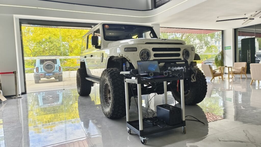
Industrial 3D inspection uses 3D scanning, point cloud processing, and CAD comparison to support dimensional inspection, deviation visualization, quality review, and traceable reporting in manufacturing.
Definition
Industrial 3D inspection is a non-contact 3D metrology technology used for quality control in industrial manufacturing. It collects full-surface 3D geometric data of the workpiece under test, performs comparative analysis against a CAD design model or standard part model, and completes qualification judgment and deviation visualization for indicators such as dimensions, GD&T (Geometric Dimensioning and Tolerancing), assembly gaps, and wear loss. It can support quality verification for parts ranging from precision components to large structural parts, and is one component of digital quality management systems in advanced manufacturing.
Working Principle
A typical industrial 3D inspection workflow can be divided into five stages:
- Data Acquisition Stage: Optical sensing technologies such as laser or structured light are used to project a characteristic light field onto the surface of the test object. An industrial camera collects reflected signals to calculate 3D point cloud data of the test object's surface. For large-size workpiece inspection scenarios, an optical tracking system can be equipped to assist with global positioning and multi-station data stitching.
- Data Preprocessing Stage: Processes such as denoising, simplification, and hole filling are performed on the raw point cloud to remove invalid data caused by environmental interference or scanning jitter, and retain valid geometric features.
- Alignment and Registration Stage: The preprocessed point cloud data is aligned with the CAD design model or 3D model of the standard part via feature alignment or best-fit alignment, to establish a unified inspection benchmark.
- Inspection and Analysis Stage: Features of the test object such as dimensions, GD&T, hole positions, and assembly gaps are extracted, and deviation values are calculated by comparison with design standards. Full-surface deviation is presented via color mapping.
- Report Output Stage: A traceable inspection report containing inspection items, deviation values, and qualification judgment results is generated in accordance with industry specifications or enterprise quality requirements.
Key Parameters and Judgment Criteria
The performance parameters of industrial 3D inspection need to be comprehensively evaluated in combination with the characteristics of the test object, application scenarios, and production requirements. The actual performance of most parameters is affected by factors such as the material of the test object, dimensional complexity, environmental conditions, and workflow configuration. The parameters and judgment criteria are as follows:
| Parameter | Definition | Judgment Method |
|---|---|---|
| Inspection Accuracy | The maximum allowable deviation between the inspection result and the true geometric dimension of the test object, which is the indicator for judging whether the inspection result has metrological validity | Use metrologically calibrated gauge blocks, standard spheres, or standard workpieces, perform repeated measurements multiple times under specified environmental conditions, and calculate the deviation range between the measured value and the standard value |
| Point Cloud Resolution | The number of valid 3D points collected per unit area, which determines the minimum feature size that can be captured | Count the number of valid point clouds in a specified standard sampling area, and evaluate suitability in combination with the size of the minimum inspection feature of the test object |
| Global Stitching Error | The cumulative position deviation of the full model after the stitching of multi-station, multi-view scan data is completed | Select common standard features across at least 2 scanning stations, and compare the deviation between their stitched measured value and the true standard value |
| Environmental Stability | The accuracy retention capability of the inspection system under industrial site environments such as varying temperature and humidity, lighting, and vibration | Under controlled conditions simulating different industrial site environments, repeatedly measure the same standard workpiece, and count the fluctuation range of accuracy |
| Inspection Efficiency | The total time required to complete the full process of inspecting a single workpiece from data acquisition to report issuance | Record the total time taken for repeated full-process inspections of the same standard workpiece, and evaluate suitability in line with production cycle requirements |
Applicable and Inapplicable Scenarios
Applicable Scenarios
- Dimensional, GD&T, and assembly accuracy inspection of various small and medium-sized industrial components
- Full-dimensional deviation verification and assembly gap inspection of large structural parts and complete equipment
- Evaluation of forming quality and wear loss in fields such as precision casting, 3D printing, and mold manufacturing
- Offline/online quality inspection under industrial site conditions such as temperature and humidity fluctuations, lighting, and vibration
- First article inspection, in-process patrol inspection, and finished product full inspection in mass production links
Inapplicable Scenarios
- Non-industrial application scenarios such as human body scanning and human facial scanning
- Clinical applications for medical image diagnosis
Common Misconceptions
- Higher accuracy is always better: Inspection accuracy needs to match the design tolerance requirements of the test object. Excessively high accuracy will increase inspection costs, reduce inspection efficiency, and cause unnecessary resource waste.
- All 3D scanning devices can be used for industrial 3D inspection: The accuracy, stability, and environmental adaptability of ordinary consumer-grade or cultural and creative 3D scanning devices do not meet industrial metrology-level requirements, and their results usually cannot be used on their own as a reliable basis for industrial quality judgment.
- Industrial 3D inspection can completely replace traditional inspection methods: For scenarios with requirements for ultra-deep microholes, internal hidden structures, or ultra-high-precision contact measurement, it is still necessary to combine other inspection technologies such as CMM (Coordinate Measuring Machine) and industrial CT for supplementary verification.
- Inspection results are not affected by the environment and the state of the test object: Test objects with highly reflective, transparent, or light-absorbing materials, as well as factors such as environmental temperature and humidity fluctuations, strong lighting, and vibration, will affect the accuracy of data acquisition, so surface preprocessing or environmental control is required in advance.
Related Concepts
3D scanning, metrology-grade 3D measurement, GD&T (Geometric Dimensioning and Tolerancing), point cloud data processing, model comparison, optical tracking, automated 3D inspection, structured light 3D scanning, laser 3D scanning
FAQ
What is the difference between industrial 3D inspection and traditional CMM inspection?
Industrial 3D inspection is a non-contact inspection method, which usually has higher efficiency for complex curved surface or large-area surface inspection. It can obtain full-surface 3D data to realize deviation visualization, and is suitable for rapid full-dimensional inspection of complex curved surfaces and large workpieces. CMM inspection is a contact inspection method, which still has advantages for regular feature and single-point measurement, but has low inspection efficiency and can only obtain limited sampling point data, making it suitable for sampling inspection of high-precision regular features.
What factors affect the accuracy of industrial 3D inspection?
Influencing factors include the metrological accuracy grade of the inspection equipment itself, the surface material state of the test object (such as high reflectivity, light absorption, and transparency characteristics), environmental temperature and humidity, lighting and vibration conditions, the stitching method of scanning stations, and the algorithm accuracy of data preprocessing and alignment.
Can industrial 3D inspection reports support quality traceability?
When the inspection system is properly calibrated and the inspection process follows the relevant industry or enterprise quality requirements, the output report can serve as one part of quality traceability documentation. Its practical validity depends on equipment calibration status, inspection procedure, acceptance criteria, and the quality system used in the relevant field.
Is additional auxiliary system configuration required for inspection of large and complex structural parts?
For workpieces with large size spans and complex structures, or scenarios where inspection is carried out in moving or vibrating environments, an optical tracking system can be equipped to assist with global positioning, reduce multi-station stitching errors, and improve the stability and efficiency of inspection.
Summary
Industrial 3D inspection is suitable for manufacturing scenarios where 3D data supports dimensional inspection, deviation analysis, and quality review. Its actual performance depends on the measurement scheme, equipment calibration, fixture clamping, test surface state, and the verification method of the inspection software.
- What Is 3D Scanning? Principles, Workflow, and Industrial Applications 3D scanning is a digital measurement technology that converts the surface geometry of physical objects into 3D data. This entry covers its working principles, core parameters, industrial use cases, common misconceptions, and related technical…
- What Is a 3D Scanner? Types, Parameters, and Selection Criteria A 3D scanner captures three-dimensional surface data from physical objects and converts geometry, dimensions, and features into digital data for inspection, reverse engineering, and modeling.
- What Is 3D Scanning Accuracy? Accuracy, Repeatability, and Resolution Explained 3D scanning accuracy describes how closely scan data matches an object's actual geometry and dimensions. It is assessed through local accuracy, volumetric accuracy, stitching accuracy, repeatability, and resolution.
- What Is Point Cloud Data? Point Clouds, Meshes, and CAD Models in 3D Scanning Point cloud data is an important raw data format in 3D scanning. It consists of discrete 3D coordinate points that describe object surface geometry and support inspection, reverse engineering, modeling, and archiving.
Hangzhou Insvision Technology Co., Ltd.
Address: Building 1, No. 1399 Liangmu Road, Yuhang District, Hangzhou, Zhejiang 311121, China
Copyright © Hangzhou Insvision Technology Co., Ltd. All rights reserved.
Copyright © Hangzhou Insvision Technology Co., Ltd. All rights reserved.