

Surface Preparation for 3D Scanning
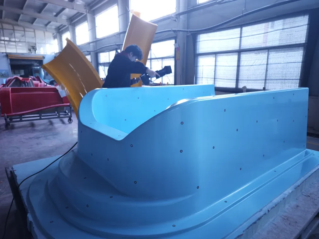
Surface preparation for 3D scanning is a standardized set of pre-scanning processes applied to a physical object’s exterior to enable consistent, accurate, and complete capture of 3D spatial data by optical, laser, or structured light scanning systems.
Definition
Surface preparation for 3D scanning is a standardized set of pre-scanning processes applied to a physical object’s exterior to enable consistent, accurate, and complete capture of 3D spatial data by optical, laser, or structured light scanning systems. It addresses inherent surface properties or temporary conditions that would otherwise introduce measurement error, missing data, or registration failures, and is tailored to the specific scanning technology, part material, accuracy requirements, and downstream use case. Common industrial applications that rely on targeted surface preparation include dimensional inspection, reverse engineering, additive manufacturing pre-processing, and quality control.
How It Works
All 3D scanning technologies that rely on light projection or reflection to calculate spatial coordinates require consistent, predictable interaction between the scanning system’s light source and the target surface. Surface preparation modulates surface properties that disrupt this interaction, including high specular reflectivity, transparency, translucency, lack of distinct geometric features, and presence of extraneous debris or surface features not intended for capture. Typical preparation steps, selected based on project requirements, include:
- Surface cleaning: Removal of oil, dust, rust, loose coatings, adhesive residue, or release agents that create false surface geometry or inconsistent light return, which would introduce noise into scan data.
- Opacification: Application of a thin, uniform temporary matte coating to transparent (glass, clear resin), highly reflective (polished metal, carbon fiber, chrome), or translucent surfaces to create a diffuse light-reflecting layer that enables consistent light detection by the scanning system.
- Registration support: Placement of temporary fiducial markers or texture patterns on or around the part to provide reference points for aligning multiple scan passes, especially for large or geometrically featureless workpieces where feature-based alignment would not be reliable.
- Masking: Coverage of non-target features (fixtures, clamping hardware, surface damage not intended for capture) to exclude extraneous data from the final scan output and reduce post-processing effort.
Properly executed preparation balances data capture quality with ease of post-scan cleanup to avoid damage to the target part.
Key Parameters and Criteria
Surface preparation quality is evaluated against measurable parameters aligned with the project’s required scan accuracy, part material, and downstream use case. Acceptable thresholds for each parameter vary based on scanning technology resolution, object size, and tolerance requirements; for example, micron-level metrology scans require stricter coating uniformity than low-resolution scanning for large asset documentation. Key evaluation parameters are outlined in the table below:
| Parameter | Meaning | Judgment Method |
|---|---|---|
| Coating Uniformity | The thickness consistency of temporary opacifying layers applied to modify surface light reflection | Visual inspection under diffused, consistent lighting; dry film gauge measurement for micron-level accuracy applications |
| Fiducial Placement Accuracy | The positional deviation of registration markers from their intended reference locations | Calibrated caliper or coordinate measuring machine (CMM) verification of marker center spacing against reference CAD or physical layout drawings |
| Surface Contamination Level | The presence of residual oil, dust, debris, or release agents that alter surface geometry or light reflectivity | Lint-free cloth wipe test; ultraviolet (UV) light inspection for hydrocarbon residues in high-accuracy metrology workflows |
| Masking Edge Sharpness | The clarity of the boundary between masked non-target areas and scannable part surfaces | 10x magnification visual inspection for edge dimension accuracy requirements below 0.1mm; unaided visual check for general use cases |
Suitable and Unsuitable Scenarios
Suitable Scenarios
- Scanning of highly reflective polished metal, carbon fiber composite, or chrome-plated parts for dimensional inspection or reverse engineering, where unmodified surfaces would cause specular reflection and missing scan data.
- Scanning of transparent or translucent components (architectural glass, medical device components, clear 3D printed resin) for geometry validation, where unmodified surfaces would refract light and produce distorted coordinate data.
- Large, geometrically uniform workpieces (wind turbine blades, automotive body panels, aerospace structural components) requiring alignment of multiple scan passes across a large volume.
- High-accuracy metrology applications where measurement uncertainty must be minimized to meet tight tolerance requirements.
- Batch scanning of identical parts where standardized surface preparation reduces per-part scan setup time and improves data consistency across the batch.
Unsuitable Scenarios
- Scanning of porous or delicate surfaces (fragile ceramic components, low-density foam, historical artifacts) where temporary coatings or adhesives for markers cannot be removed without damaging the part.
- Applications requiring capture of fine surface texture (wear pattern analysis, decorative surface inspection, forensic scanning) where coatings or markers would obscure the target surface features.
- High-throughput in-line production scanning workflows where pre-processing time would reduce line efficiency, and on-board scanning algorithms can compensate for minor variations in surface reflectivity.
- Scanning of food, pharmaceutical, or biocompatible components where temporary coatings or marker adhesives would introduce contamination risks.
Common Misconceptions
- Misconception: All 3D scanning projects require full surface opacification.
Correction: Opacifying coatings are only required for surfaces that cause specular reflection, refraction, or light scattering that scanning hardware and software cannot compensate for. Many matte, diffuse surfaces (e.g., cast iron, injection-molded matte plastic) require no coating beyond basic cleaning to produce high-quality scan data.
- Misconception: Thicker opacifying coatings improve scan data quality.
Correction: Excess coating thickness adds unintended geometric deviation to scan data, which can exceed acceptable accuracy thresholds for metrology applications. Opacifying coatings are designed to be as thin and uniform as possible to modify light reflection without altering the underlying part geometry.
- Misconception: Fiducial markers are mandatory for all scan registration.
Correction: Fiducial markers are only necessary for parts with insufficient distinct geometric features to support feature-based alignment, or for multi-scan setups where optical tracking systems lack sufficient reference points in the scan volume. Feature-rich parts can often be aligned accurately without markers using built-in scan registration algorithms.
- Misconception: Surface preparation follows a single universal workflow for all scanning projects.
Correction: Preparation steps are fully tailored to the scanning technology, part material, required measurement accuracy, and downstream use case. A workflow suitable for low-resolution large-asset scanning may not meet the requirements for high-resolution blue light metrology scanning, and vice versa.
Related Concepts
- 3D Scan Registration: The process of aligning multiple individual scan passes into a single unified 3D point cloud or mesh, which often relies on surface features or reference markers applied during surface preparation.
- Optical Tracking: A measurement method that uses calibrated cameras to track the position of reference markers or scanning hardware in 3D space, which may require targeted surface or environment preparation to ensure consistent marker detection.
- Structured Light 3D Scanning: A scanning technology that projects patterned light onto a surface to calculate spatial coordinates, which is particularly sensitive to surface reflectivity and transparency, making targeted surface preparation common for high-accuracy use cases.
- Dimensional Metrology: The practice of precise physical measurement for quality control or compliance, where surface preparation is used to reduce measurement uncertainty and ensure scan data meets specified tolerance requirements.
- Reverse Engineering: The process of generating a parametric CAD model from a physical part, which relies on complete, low-noise scan data often enabled by targeted surface preparation.
FAQ
What types of temporary coatings are commonly used for 3D scanning surface preparation?
Common temporary opacifying coatings include water-soluble matte sprays, chalk-based dry powders, and solvent-based removable matte treatments. Selection depends on part material, required coating thickness, ease of post-scan removal, and compatibility with downstream part use. For example, water-soluble sprays are often used for metal parts that can be safely rinsed post-scanning, while dry powders may be preferred for delicate porous surfaces where liquid coatings would cause damage or discoloration.
Can surface preparation introduce errors into 3D scan data?
Yes, if applied incorrectly. Common sources of preparation-related error include uneven coating thickness, misaligned fiducial markers, residual contamination left during cleaning, and masking that covers critical part features. When performed to defined specifications aligned with the project’s accuracy requirements, these errors are typically negligible relative to the targeted measurement tolerance.
Is surface preparation required for automated 3D scanning workflows?
It depends on the workflow design, part material consistency, and required scan accuracy. Automated scanning systems may integrate AI-powered reflectivity compensation algorithms to adjust for minor surface variations, reducing or eliminating preparation needs for parts with consistent, diffuse surfaces. For high-accuracy automated inspection of reflective or transparent parts, standardized surface preparation steps are often integrated into the workflow prior to scanning to ensure consistent data quality.
How should temporary coatings be removed after scanning is complete?
Removal methods vary by coating type. Water-soluble sprays are typically removed with clean water rinsing or wiping with a damp lint-free cloth. Dry chalk-based powders can be brushed off or removed with low-pressure compressed air. Solvent-based coatings require compatible cleaning agents that do not damage the underlying part surface. All removal processes are validated prior to use to avoid part damage or residual coating left on functional surfaces.
Summary
Surface preparation for 3D scanning is a configurable set of pre-scanning processes designed to optimize surface properties for accurate, complete, and consistent 3D spatial data capture, tailored to the specific scanning technology, part material, accuracy requirements, and downstream application. It addresses common scanning challenges including high specular reflectivity, transparency, low feature contrast, and surface contamination, with its scope and rigor varying widely based on use case parameters. Properly executed surface preparation reduces scan registration errors, minimizes post-processing time, and lowers measurement uncertainty for industrial 3D scanning applications ranging from dimensional inspection and quality control to reverse engineering and additive manufacturing pre-processing.
- What Is 3D Scanning? Principles, Workflow, and Industrial Applications 3D scanning is a digital measurement technology that converts the surface geometry of physical objects into 3D data. This entry covers its working principles, core parameters, industrial use cases, common misconceptions, and related technical…
- What Is a 3D Scanner? Types, Parameters, and Selection Criteria A 3D scanner captures three-dimensional surface data from physical objects and converts geometry, dimensions, and features into digital data for inspection, reverse engineering, and modeling.
- What Is 3D Scanning Accuracy? Accuracy, Repeatability, and Resolution Explained 3D scanning accuracy describes how closely scan data matches an object's actual geometry and dimensions. It is assessed through local accuracy, volumetric accuracy, stitching accuracy, repeatability, and resolution.
- What Is Point Cloud Data? Point Clouds, Meshes, and CAD Models in 3D Scanning Point cloud data is an important raw data format in 3D scanning. It consists of discrete 3D coordinate points that describe object surface geometry and support inspection, reverse engineering, modeling, and archiving.
Hangzhou Insvision Technology Co., Ltd.
Address: Building 1, No. 1399 Liangmu Road, Yuhang District, Hangzhou, Zhejiang 311121, China
Copyright © Hangzhou Insvision Technology Co., Ltd. All rights reserved.
Copyright © Hangzhou Insvision Technology Co., Ltd. All rights reserved.