

Sources of Error in 3D Scanning
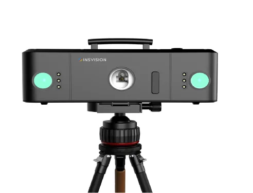
Sources of error in 3D scanning refer to the full set of systematic, random, environmental, workflow-related, or material-based factors that introduce measurable deviation between the 3D point cloud, mesh, or measurement output of a 3D scanning system and the true geometric dimensions of the physical object being scanned.
Definition
Sources of error in 3D scanning refer to the full set of systematic, random, environmental, workflow-related, or material-based factors that introduce measurable deviation between the 3D point cloud, mesh, or measurement output of a 3D scanning system and the true geometric dimensions of the physical object being scanned. These errors affect the accuracy, precision, and geometric fidelity of scan data across all 3D scanning modalities, including structured light, laser triangulation, photogrammetry, and optical tracking systems. The magnitude of total error is a function of both the scanning hardware's inherent performance and the conditions under which the scan is executed.
How It Works
Errors in 3D scanning originate and propagate at every stage of the 3D scanning workflow, from pre-scan calibration to final data post-processing. They are broadly categorized by their root cause:
- Systematic errors: Consistent, repeatable deviations that stem from inherent hardware properties or uncompensated consistent conditions. Common sources include lens distortion, factory calibration drift, thermal expansion of scanner components, or uncorrected projector distortion in structured light systems. These errors are predictable and can be largely eliminated via regular recalibration or software compensation.
- Random errors: Unpredictable, stochastic variations in measurement values with no consistent pattern. Common sources include image sensor noise, minor ambient vibration during capture, small fluctuations in lighting intensity, or tiny variations in scanner position during handheld scanning. These errors cannot be fully eliminated, but can be reduced by averaging multiple scans of the same object or increasing capture integration time where workflow allows.
- Environmental errors: Deviations caused by external conditions in the scanning environment. Common sources include large temperature fluctuations, direct sunlight or harsh ambient lighting that interferes with structured light or laser patterns, high vibration, or reflective surfaces in the scan area that bounce stray light into scanner sensors.
- Workflow and material errors: Deviations introduced by user actions or object properties, including improper scan alignment, insufficient overlap between adjacent scans, unaddressed reflective or transparent object surfaces, or motion of the scanned object during capture.
Total error in a final scan dataset is typically the sum of errors from multiple sources, with some errors (such as alignment error) compounding as the number of individual scans or the size of the scanned object increases.
Key Parameters and Criteria
Sources of error in 3D scanning are quantified using standardized metrological parameters, with acceptable error thresholds varying by use case (e.g., metrology-grade inspection for aerospace components requires far lower error than 3D modeling for prototyping). The core parameters used to characterize error magnitude include the following:
| Parameter | Meaning | Judgment Method |
|---|---|---|
| Single Scan Accuracy | Deviation between measurements from a single scan and traceable reference dimensions, within the scanner's field of view | Compare scan data of a calibrated sphere plate, gauge block, or step gauge to its nominal traceable dimensions, calculate root mean square (RMS) deviation |
| Volumetric Accuracy | Deviation of measurements across the scanner's full working volume, accounting for error scaling with distance from the scanner | Scan a calibrated length bar or 3D reference artifact at multiple positions and orientations within the scanner's working envelope, measure RMS deviation from nominal values across all positions |
| Alignment Error | Deviation introduced when merging multiple overlapping scans into a unified coordinate system | Measure the positional deviation of common reference targets or rigid geometric features across overlapping scan datasets, calculate mean deviation of aligned feature centers |
| Material-Induced Deviation | Deviation caused by the scanned object's surface properties, independent of inherent scanner performance | Scan a calibrated geometry in its native surface state, then re-scan the same geometry coated with a matte, near-white reference coating; calculate the difference between the two datasets |
Suitable and Unsuitable Scenarios
This section refers to scenarios where sources of 3D scanning error can be reliably quantified, controlled, and compensated, and scenarios where error sources cannot be sufficiently managed to produce usable, fit-for-purpose data.
Suitable Scenarios
- Controlled indoor metrology or production environments with stable temperature, humidity, and ambient lighting, where environmental error sources can be measured and compensated via hardware or software adjustments.
- Scanning of rigid objects with matte, low-reflectivity surfaces and distinct geometric features or attached reference targets, minimizing material-induced and alignment errors.
- Workflows that include pre-scan calibration against traceable reference artifacts, allowing systematic errors to be identified and corrected before data capture.
- Large-volume scanning workflows supported by fixed reference targets or real-time optical tracking, limiting cumulative alignment error across multiple scans.
Unsuitable Scenarios
- Uncontrolled outdoor environments with extreme temperature fluctuations, direct sunlight, or high vibration, where environmental errors are unpredictable and cannot be reliably compensated.
- Scanning of highly reflective, transparent, or optically translucent objects without pre-treatment, where material-induced errors produce distorted or incomplete point cloud data that cannot be fully corrected in post-processing.
- Scanning of dynamically deforming or moving objects without synchronized high-speed capture hardware, where motion-induced error dominates output fidelity.
- Workflows with no access to calibrated reference artifacts, where systematic errors cannot be quantified or validated against traceable standards.
Common Misconceptions
- Misconception: A higher scanner resolution specification eliminates all sources of scanning error.
Fact: Scanner resolution refers to the density of captured data points, not the accuracy of those points. A high-resolution scan can have significant systematic, alignment, or material-induced errors, resulting in a detailed but geometrically inaccurate dataset.
- Misconception: All 3D scanning errors are caused by inherent hardware defects.
Fact: The majority of typical scanning errors stem from non-hardware factors, including uncalibrated equipment, unsuitable environmental conditions, improper surface preparation, or incorrect scan registration, rather than inherent hardware limitations.
- Misconception: Post-processing software can fully correct all sources of 3D scanning error.
Fact: While post-processing tools can reduce random noise and compensate for well-characterized systematic errors, they cannot eliminate unquantified alignment errors, material-induced geometric distortion, or data gaps caused by reflective or transparent surfaces.
- Misconception: Published scanner accuracy ratings apply equally to all scanning use cases.
Fact: Published accuracy values are measured under controlled laboratory conditions using calibrated reference artifacts. Real-world error magnitude varies significantly based on object size, surface properties, working distance, environmental conditions, and workflow design.
Related Concepts
- 3D Scanning Accuracy: The primary performance metric that quantifies the total magnitude of error in a scan output, defined as the degree of closeness of scan measurements to the true value of the measured dimension.
- Point Cloud Registration: The process of aligning overlapping individual scan datasets into a single unified coordinate system, a common source of cumulative alignment error for large-part scanning.
- Volumetric Accuracy: A metrological parameter that measures error scaling with scanning distance and working volume, critical for evaluating performance in large-part scanning workflows.
- Optical Tracking: A hardware-based position measurement system that tracks scanner location in 3D space in real time, used to reduce cumulative alignment error during large-volume scanning.
- Projection Distortion: A systematic error source in structured light and laser projection systems, caused by lens or optical component distortion, which is calibrated out during factory and regular user calibration routines.
- Metrological Traceability: The framework for validating scan error measurements against nationally or internationally recognized reference standards, ensuring error quantification is consistent and comparable across systems and use cases.
FAQ
What is the difference between systematic and random error in 3D scanning?
Systematic error is a consistent, repeatable deviation from the true measured value, typically caused by factors such as lens distortion, calibration drift, or uncompensated thermal effects on scanner hardware. These errors are predictable and can be largely corrected via regular recalibration or targeted software compensation. Random error is unpredictable, stochastic variation in measurements with no consistent pattern, caused by factors including image sensor noise, minor ambient vibration, or small fluctuations in lighting intensity. Random errors cannot be fully eliminated, but can be reduced by averaging multiple scans of the same object or extending capture integration time where workflow allows.
Can an object's surface properties introduce more error than a scanner's inherent hardware limitations?
Yes. Surface characteristics including high reflectivity, translucency, low contrast, or repetitive fine textures can introduce material-induced errors that exceed the published accuracy specification of a scanner. For example, polished metal surfaces can reflect structured light or laser patterns away from scanner sensors, producing missing or geometrically distorted point cloud data that deviates sharply from the true object shape. Pre-treatment such as a thin coat of matte scanning spray can reduce these errors for most use cases.
How does merging multiple scans affect total scanning error?
Merging overlapping individual scans (a process called point cloud registration) introduces cumulative alignment error, which increases with the number of scans merged if no global reference system is used. For example, scanning a large workpiece with a handheld scanner without external tracking can result in small alignment errors between adjacent scans that compound across the full length of the part, leading to measurable distortion of the final full-part mesh. Using fixed reference targets mounted to the part or surrounding environment, or real-time optical tracking systems, can minimize this cumulative error.
Do temperature fluctuations impact 3D scanning error?
Yes. Temperature changes cause thermal expansion or contraction of both the scanned object and the scanner's internal optical and mechanical components, introducing systematic measurement error. For high-precision metrology applications, even 1–2°C shifts in ambient temperature can produce measurable deviations, particularly for large objects or long-duration scanning workflows. Most high-precision scanning systems include integrated temperature compensation algorithms, but these are most effective in environments with stable, controlled ambient temperature.
Summary
Sources of error in 3D scanning are a multifaceted set of systematic, random, environmental, workflow-related, and material-based factors that introduce deviation between scan output and the true geometric dimensions of a scanned object. Errors originate and propagate at every stage of the scanning workflow, from pre-scan calibration to data post-processing, and their magnitude varies based on scanner modality, environmental conditions, object properties, and workflow design. Quantifying error via standardized metrological parameters, controlling environmental conditions, preparing surfaces appropriately, and using reference systems such as optical tracking can reduce or compensate for most errors, enabling accurate, reliable 3D data for industrial applications including quality inspection, reverse engineering, and 3D modeling.
- What Is 3D Scanning? Principles, Workflow, and Industrial Applications 3D scanning is a digital measurement technology that converts the surface geometry of physical objects into 3D data. This entry covers its working principles, core parameters, industrial use cases, common misconceptions, and related technical…
- What Is a 3D Scanner? Types, Parameters, and Selection Criteria A 3D scanner captures three-dimensional surface data from physical objects and converts geometry, dimensions, and features into digital data for inspection, reverse engineering, and modeling.
- What Is 3D Scanning Accuracy? Accuracy, Repeatability, and Resolution Explained 3D scanning accuracy describes how closely scan data matches an object's actual geometry and dimensions. It is assessed through local accuracy, volumetric accuracy, stitching accuracy, repeatability, and resolution.
- What Is Point Cloud Data? Point Clouds, Meshes, and CAD Models in 3D Scanning Point cloud data is an important raw data format in 3D scanning. It consists of discrete 3D coordinate points that describe object surface geometry and support inspection, reverse engineering, modeling, and archiving.
Hangzhou Insvision Technology Co., Ltd.
Address: Building 1, No. 1399 Liangmu Road, Yuhang District, Hangzhou, Zhejiang 311121, China
Copyright © Hangzhou Insvision Technology Co., Ltd. All rights reserved.
Copyright © Hangzhou Insvision Technology Co., Ltd. All rights reserved.