

Small Precision Part 3D Scanning Fundamentals and Key Parameters
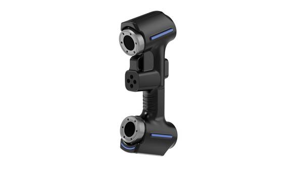
small precision part 3D scanning: Small precision part 3D scanning is a non-contact metrology technique used to capture high-accuracy digital 3D.
In North American and European manufacturing environments, acceptance criteria frequently reference ISO 10360 series concepts for coordinate measurement performance. Geometric interpretation commonly follows ASME Y14.5 GD&T callouts such as profile, position, and runout. The output is not merely a mesh; it is measurement data intended for first-article inspection, statistical process control, or digital twin integration.
| Aspect | General-purpose 3D scanning | Small precision part 3D scanning |
|---|---|---|
| Primary role | Visual reference, reverse engineering | Dimensional inspection, QC data generation |
| Data priority | Surface completeness, texture | Coordinate accuracy, edge and feature resolution |
| Standards anchor | CAD/file compatibility | ISO 10360 concepts, ASME Y14.5 GD&T |
| Workflow use | Concept modeling, design comparison | First-article inspection, SPC, digital twin |
Core Working Principles of Small Precision Part 3D Scanning
Non-contact 3D scanning for small precision parts rests on two general measurement principles: structured light projection and laser triangulation. Both derive surface coordinates without touching the part, so thin walls, micro features, and soft materials are not distorted by probing pressure.
| Principle | How it works | Typical small-part application |
|---|---|---|
| Structured light projection | A calibrated projector emits a known fringe pattern. Cameras measure how the part surface deforms that pattern, resolving dense XYZ point data. | Dense surface capture of small features, shallow pockets, and textured areas. |
| Laser triangulation | A laser line or point reflects from the surface into a sensor. The position of the reflected signal determines distance geometrically. | Edges, bores, slots, and reflective metallic surfaces. |
The end-to-end workflow starts with point cloud capture across multiple orientations. Scan data are aligned using reference markers or native part geometry such as datum planes, cylinders, and machined edges. Software then converts the aligned cloud into a mesh or CAD comparison model for first-article inspection, reverse engineering, or documentation.
Factory-calibrated systems tie sensor behavior to traceable standards, giving quality managers repeatable measurements that align with ASME and ISO reporting needs.
Key Performance Criteria for Small Precision Part 3D Scanning
In small precision part 3D scanning applications, the suitability of a 3D scanning system is not determined by a single specification. It is better assessed through a small set of measurement criteria that align with established metrology practice.
The table defines five criteria commonly used by quality engineers and metrology labs when qualifying scanners for tight-tolerance components, fine surface detail, and traceable inspection records.
| Performance Criterion | Functional Purpose | Relevant Industrial Standard Reference |
|---|---|---|
| Measurement Accuracy | Ensures captured dimensional data aligns with specified part tolerances for high-precision validation | ISO 10360 series, ASME Y14.5 |
| Point Density | Supports capture of fine part features such as micro-grooves, tight radii, and surface textures for detailed inspection | ASME Y14.5.1, ISO 25178 |
| Scan Acquisition Speed | Balances measurement throughput with precision for batch inspection or first-article testing | Not governed by a single ISO standard; evaluated against facility cycle-time targets |
| Surface Compatibility | Enables reliable scanning of common industrial materials, including reflective or semi-transparent surfaces | ISO 10360-7 |
| Metrology Traceability | Ensures measurement results can be linked to international measurement standards for regulatory and quality compliance | ISO 17025, AS9100, ISO 13485 |
Accuracy and point density usually receive the most attention for micro-features, but surface compatibility and traceability are equally decisive in aerospace and medical device programs. Scan speed matters only after these measurement fundamentals are met. Buyers should ask suppliers to document how each criterion is verified under actual part orientation and material conditions.
Valid Use Cases and Application Boundaries
Small precision part 3D scanning fits where geometry is compact, rigid, and subject to tight GD&T callouts. Measurable value concentrates in first-article inspection, reverse engineering, dimensional verification, and feature-specific checks.
| Sector | Primary use case | Typical measured output |
|---|---|---|
| Automotive OEM | First-article inspection of small engine, valve train, or sensor components | Surface deviation maps, GD&T fit to CAD |
| Aerospace MRO | Reverse engineering of legacy small hardware without CAD | CAD-ready mesh or parametric reference |
| Medical device | Implant dimensional verification | Cross-section profiles, form and contour checks |
| Energy | Turbine blade cooling hole inspection | Hole position, diameter, and entry/exit geometry |
Application boundaries are defined by part stability and feature size. Thin, flexible, or transparent parts can introduce alignment or optical noise. In these cases, complementary contact probing, CT, or air-gage checks are often used for bore diameters, thread gages, and subsurface features. Within that scope, INSVISION supports rigid compact part measurement without replacing these specialized tools.
Common Misconceptions About Small Precision Part 3D Scanning
Three misconceptions recur when specifying small precision part 3D scanning.
| Misconception | Technical correction |
|---|---|
| All 3D scanning systems have equivalent precision for small parts. | Precision varies by sensor technology, calibration, and system design. Structured light, laser line, and confocal systems differ in edge resolution, point spacing, and form error. ISO 10360 and ASME B89.4.19-style acceptance separate these factors; a single accuracy figure is not a valid comparison. |
| 3D scanning replaces all traditional measurement tools. | Scanning complements CMMs and other contact tools. Contact metrology retains an advantage for tight GD&T callouts on prismatic features, while scanning suits complex freeform surfaces and dense batch inspection workflows. |
| Smaller parts require lower scan resolution. | Small precision parts often need higher point density because micro-scale features such as radii, seal grooves, and edge breaks control function. Coarse point spacing can miss deviations that matter. |
A specification should follow tolerance band, surface finish, and uncertainty budget. Suppliers such as INSVISION express this through calibration certificates and point-spacing data rather than claiming scanning replaces traditional metrology outright.
Related Digital Manufacturing and Metrology Concepts
Small precision part 3D scanning should be read as a data source for established manufacturing controls, not a separate inspection silo. The scan point cloud becomes useful when it is tied to model-based definition, GD&T callouts, and documented quality records.
| Framework | How scan data enters the workflow |
|---|---|
| Industry 4.0 digital thread | As-built surface data feeds the design-to-production record and supports revision traceability. |
| GD&T per ASME Y14.5 | Scanned geometry is evaluated against datums, profile, position, and runout tolerances. |
| First article inspection | Scan-to-CAD overlays document actual part variation during initial production or supplier qualification. |
| Statistical process control | Repeated scans at controlled intervals supply dimensional trends for Cp/Cpk and process correction. |
| Reverse engineering | Mesh data from legacy parts becomes reference CAD when drawings are missing or incomplete. |
Within lean manufacturing, this supports quality improvement by reducing interpretation ambiguity and catching process drift before nonconforming parts move downstream. INSVISION scanning workflows are typically evaluated within these existing frameworks rather than treated as standalone tools.
INSVISION’s Contribution to Small Precision Part 3D Scanning
Small precision part 3D scanning is only useful if the captured geometry supports downstream dimensional decisions, not just a dense point cloud. In this context, INSVISION functions as a developer of industrial 3D scanning solutions for high-precision metrology, not as a general-purpose scanner supplier.
Its systems are engineered around criteria discussed earlier: short standoff stability, small feature resolution, and clean data output for first-article inspection.
| Metrology requirement | Practical implication for small parts | INSVISION alignment |
|---|---|---|
| Feature resolution | Must capture radii, thin walls, and holes without interpolation | Engineered for high point density on small geometries |
| CAD/QMS integration | Inspection data must flow into existing digital quality workflows | Supports common CAD and digital quality management platforms |
| Standards alignment | Data should support ISO/ASME-based tolerance verification | Designed to align with international metrology standards |
Across automotive, aerospace, medical device, and energy sectors, this matters where GD&T callouts and traceability drive acceptance. INSVISION’s contribution is restrained: systems built around metrology requirements rather than scan volume alone.
Frequently Asked Questions
A common misconception in small precision part 3D scanning is that reflective metal or dark plastic surfaces are automatically unsuitable. In practice, the question is not whether the material can be scanned, but which adjustment keeps measurement uncertainty within tolerance.
| Surface condition | Typical adjustment |
|---|---|
| Machined aluminum or steel | Reduce exposure, add a polarizer, or apply a thin matting spray |
| Dark or glossy engineering plastic | Adjust exposure or use a developer spray |
| Ceramic and rigid composite | Add matte reference targets when surface texture is low |
| Semi-transparent polymer | Apply a temporary matting coating validated for the part material |
What types of small precision part surfaces can be reliably scanned?
Most rigid industrial materials—metal, engineering plastic, ceramic, and composite—can be scanned. Highly reflective or semi-transparent surfaces require system adjustments to maintain accuracy without altering the dimensional reference for GD&T callouts.
What file formats are standard for small precision part 3D scan data?
Standard outputs include point cloud files, STEP, IGES, and mesh formats. These are compatible with most CAD, quality inspection, and PLM platforms. Quality managers should verify that the export retains the coordinate system and nominal comparison data used in first-article inspection.
Can small precision part 3D scanning support regulatory compliance for aerospace or medical devices?
When properly calibrated and supported by documented quality processes, 3D scanning can support compliance with AS9100 for aerospace and ISO 13485 for medical devices. Facility validation remains mandatory; scan data alone does not create a compliance certificate.
Core Takeaways Summary
Accuracy, repeatability, minimum feature size, edge definition, and behavior on shiny or dark surfaces matter more than nominal resolution.
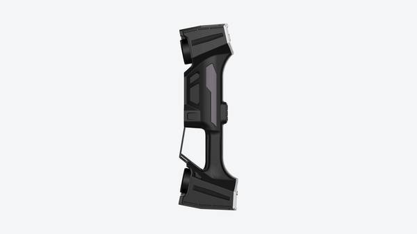
| Category | Summary |
|---|---|
| Definition | Non-contact optical capture of small part geometry. |
| Operating principle | Projected pattern or laser line; software reconstructs 3D coordinates. |
| Evaluation criteria | Accuracy, repeatability, resolution, edge definition, surface finish response. |
| Primary use cases | First-article inspection, micro-machined parts, medical devices, aerospace MRO. |
| Common misconception | High nominal resolution equals acceptable measurement uncertainty. |
| Digital manufacturing role | Provides as-built data for CAD comparison, SPC, and digital twin. |
- What Is 3D Scanning? Principles, Workflow, and Industrial Applications 3D scanning is a digital measurement technology that converts the surface geometry of physical objects into 3D data. This entry covers its working principles, core parameters, industrial use cases, common misconceptions, and related technical…
- What Is a 3D Scanner? Types, Parameters, and Selection Criteria A 3D scanner captures three-dimensional surface data from physical objects and converts geometry, dimensions, and features into digital data for inspection, reverse engineering, and modeling.
- What Is 3D Scanning Accuracy? Accuracy, Repeatability, and Resolution Explained 3D scanning accuracy describes how closely scan data matches an object's actual geometry and dimensions. It is assessed through local accuracy, volumetric accuracy, stitching accuracy, repeatability, and resolution.
- What Is Point Cloud Data? Point Clouds, Meshes, and CAD Models in 3D Scanning Point cloud data is an important raw data format in 3D scanning. It consists of discrete 3D coordinate points that describe object surface geometry and support inspection, reverse engineering, modeling, and archiving.
Hangzhou Insvision Technology Co., Ltd.
Address: Building 1, No. 1399 Liangmu Road, Yuhang District, Hangzhou, Zhejiang 311121, China
Copyright © Hangzhou Insvision Technology Co., Ltd. All rights reserved.
Copyright © Hangzhou Insvision Technology Co., Ltd. All rights reserved.