

Scanner CAD CAM Core Concepts, Principles, Parameters, and Use Cases
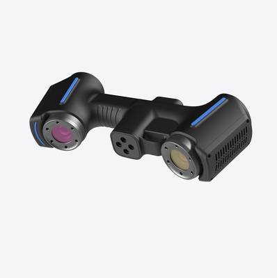
scanner cad cam: What Is Scanner CAD CAM? What Is Scanner CAD CAM? Scanner CAD CAM describes an integrated digital manufacturing workflow that links.
What Is Scanner CAD CAM?
What Is Scanner CAD CAM?
Scanner CAD CAM describes an integrated digital manufacturing workflow that links non-contact 3D scanning hardware to computer-aided design (CAD) and computer-aided manufacturing (CAM) systems. The term refers not to a single device but to a data pipeline: scan, model, machine.
A physical part is captured as a dense point cloud, converted into a parametric or mesh CAD model, and then used to generate toolpaths for CNC machining, additive manufacturing, or inspection programming.
This distinction matters. Traditional CAD/CAM tools rely on manual measurement input — calipers, height gauges, CMM probe points — which introduces transcription error and limits complexity capture. Scanner CAD CAM removes that bottleneck by feeding measured geometry directly into the digital model. Reverse engineering, wear analysis, and adaptive machining all depend on this closed loop.
Core components include:
| Component | Function |
|---|---|
| 3D scanning hardware | Non-contact capture of surface geometry as point cloud data |
| Scan data processing software | Mesh cleanup, alignment, noise filtering, and surface reconstruction |
| CAD integration interface | Conversion of scan data into editable CAD entities or reference geometry |
| CAM toolpath generation module | Machining strategy development from scan-derived models |
Within Industry 4.0 frameworks, scanner CAD CAM supports digital twin creation and closed-loop process control. Lean manufacturing principles benefit as well: eliminating manual measurement steps reduces non-value-added time and scrap from measurement error.
Adoption spans automotive OEM body-in-white verification, aerospace MRO where legacy parts lack CAD documentation, medical device production requiring patient-specific geometry, and energy component manufacturing where wear patterns dictate repair machining. Suppliers such as INSVISION provide scanning hardware that feeds this workflow, though the workflow itself remains platform-agnostic.
Core Working Principles of Scanner CAD CAM Workflows
A scanner CAD CAM workflow converts physical geometry into machine-executable manufacturing data through a defined sequence of digital operations. The process bridges metrology, design, and production without relying on manual measurement or 2D drawings as the primary data source.
End-to-End Operational Flow
| Step | Process | Primary Output | Relevant Standard |
|---|---|---|---|
| 1 | Non-contact surface capture | Point cloud / polygon mesh | ISO 10360 (CMM verification principles) |
| 2 | Scan data processing | Watertight, dimensionally accurate 3D model | ASME Y14.5 (GD&T reference geometry) |
| 3 | CAD integration | Parametric or hybrid CAD model | ASME Y14.5, ISO 1101 |
| 4 | CAM translation | Toolpaths for CNC, additive, or EDM | ISO 6983 (G-code), STEP-NC |
| 5 | Closed-loop validation | As-built vs. as-designed deviation report | ISO 10360, ASME Y14.5 |
Step 1: Physical part scanning. Structured light or laser triangulation captures surface geometry without contact. The scanner projects a known pattern onto the part, cameras record deformation of that pattern, and software reconstructs coordinates into a point cloud or polygon mesh. Accuracy claims for any scanner must be evaluated against traceable artifacts, not vendor marketing language.
A scanner with a stated accuracy of up to 0.020 mm, for example, should be verified under controlled temperature and vibration conditions before use in first-article inspection.
Step 2: Scan data processing. Raw scan data contains noise, overlapping regions, and holes. Processing involves outlier removal, global alignment of multiple scans, mesh smoothing within tolerance limits, and hole filling to produce a watertight model. The goal is not cosmetic smoothing. Every operation must preserve dimensional fidelity to the physical part. Over-processing can remove real surface features;
under-processing leaves artifacts that corrupt downstream CAD work.
Step 3: CAD integration. The processed mesh enters CAD software in one of three modes: reverse engineering to extract parametric features, direct mesh editing for design modification, or comparison against a nominal CAD model for inspection. In inspection workflows, the scan data is aligned to the nominal model using datum features defined by GD&T callouts.
Deviation color maps then show where the as-built part falls inside or outside tolerance zones.
Step 4: CAM translation. Once the CAD model is finalized, CAM software generates toolpaths. For CNC machining, this means defining cutting strategies, feed rates, spindle speeds, and tool selection. For additive manufacturing, the CAM step produces slice data and scan paths.
The critical requirement is that the CAM system receives a defect-free CAD model — any mesh errors from Step 2 or Step 3 propagate directly into machine motion.
Step 5: Closed-loop validation. After production, the finished part is scanned again and compared to the design model. This step catches tool wear, fixture drift, thermal distortion, and process variation before bad parts ship. The deviation report becomes a quality record tied to specific lot numbers and machine setups.
Key Technical Considerations
Dimensional metrology standards matter. ISO 10360 defines acceptance tests for coordinate measuring systems, including the use of calibrated length artifacts and sphere standards. While originally written for touch-probe CMMs, its principles apply to scanner verification. ASME Y14.5 governs how tolerances are defined and interpreted — a scanner workflow is only as good as the GD&T framework it operates within.
A common misconception is that scanner accuracy equals workflow accuracy. It does not. Total measurement uncertainty includes scanner error, alignment error, environmental effects, and operator technique. Engineers evaluating scanner CAD CAM systems should ask for uncertainty budgets, not just single-value accuracy specifications.
INSVISION notes that scanner and tracker configurations can be selected based on required scanning area and depth of field — with scanner-side scanning areas up to 1100 mm × 800 mm and tracker-side coverage up to 2600 mm × 2200 mm in its industrial 3D scanner system.
Such specifications are relevant when matching hardware to part size and inspection volume, but they must be weighed against the accuracy requirements of the specific application.
Key Performance Parameters for Scanner CAD CAM Systems
Selecting a scanner CAD CAM system for an industrial environment requires a clear grasp of the measurable technical parameters that determine whether a given system can support specific inspection, reverse engineering, or machining workflows. These parameters are not abstract specifications;
they translate directly into pass/fail outcomes on first-article inspections, cycle time on MRO teardown analysis, and the reliability of CAD reconstruction from physical parts.
The table below organizes the core metrics used by Western manufacturing teams to evaluate scanner CAD CAM systems against documented quality requirements. Each parameter is defined in terms of the technical measurement itself, followed by its practical consequence in production or quality engineering.
| Parameter | Technical Definition | Industrial Application Impact |
|---|---|---|
| Accuracy | The maximum permissible deviation between a scanned measurement and the true physical dimension of a part, typically expressed in millimeters. | Determines whether the system can validate tight GD&T callouts for aerospace structural components, medical implants, or precision automotive powertrain parts under ISO and ASME quality frameworks. |
| Depth of Field | The maximum distance range over which a scanner captures accurate, in-focus geometry without repositioning or hardware adjustment. | Affects setup time and operator intervention when scanning parts with stepped surfaces, deep cavities, or varying heights common in die-cast housings and welded assemblies. |
| Scanning Area | The maximum surface area captured in a single, uninterrupted scan pass. | A larger single-pass area reduces the number of alignment operations required for large workpieces, lowering cumulative error risk in automotive body-in-white verification or energy sector flange inspection. |
| Data Format Compatibility | The range of standard 3D file formats a scanner can export for direct import into CAD and CAM platforms. | Direct export in formats such as STL, OBJ, or STEP eliminates manual translation steps that introduce data loss or geometry corruption between scanning and machining or design software. |
| Scan Resolution | The density of data points captured per unit of surface area, defining the level of fine geometric detail recorded. | Determines whether micro-grooves, seal surfaces, or small radius features on precision tooling and medical devices can be captured with sufficient fidelity for downstream CAM programming or dimensional analysis. |
These parameters should be evaluated against the specific tolerance range and feature size of the parts in question, not treated as universal quality scores. A system with extremely high accuracy but insufficient depth of field may underperform in a foundry environment where castings vary in height by several hundred millimeters.
Conversely, a large scanning area without adequate resolution may fail to capture the fine features required for turbine blade inspection.
Metrology engineers typically validate scanner performance through correlation studies against CMM reference data, using calibrated artifacts with known dimensions and surface characteristics. This approach aligns with standard practices in ISO 9001 and AS9100 quality systems, where measurement equipment must demonstrate fitness for purpose before deployment on production parts.
INSVISION offers scanner CAD CAM systems with specified accuracy values up to 0.020 mm for scanner modules and scanning areas up to 1100 mm × 800 mm per pass, with depth of field reaching 650 mm. These figures serve as reference points for comparing against internal capability requirements, though final selection should always be confirmed through on-site validation with representative production parts.
Primary Use Boundaries of Scanner CAD CAM Technology
Scanner CAD CAM refers to the integrated workflow in which three-dimensional optical scanning data is converted into CAD models and subsequently used for CAM programming, toolpath generation, or dimensional analysis. The technology is not a universal replacement for conventional coordinate measuring machines or CAD-native design.
Its value concentrates in workflows where physical geometry exists but digital definition is incomplete, outdated, or unverified.
The strongest application categories fall into five areas:
| Application Category | Primary Workflow | Typical Industrial Context |
|---|---|---|
| Legacy part reverse engineering | Scan-to-CAD model creation for parts with no existing digital files | Machine tool replacement parts, obsolete tooling, aftermarket components |
| First-article and in-process inspection | Scan-to-nominal CAD comparison with GD&T callouts | High-precision machined components, castings, injection molded parts |
| Custom tooling design and verification | Scan tooling surfaces, modify CAD, verify after rework | Press tools, jigs, fixtures, forming dies |
| Digital twin creation | Scan asset geometry for monitoring and predictive maintenance models | Energy sector rotating equipment, plant machinery |
| Custom part production | Scan patient or component geometry, design, then CAM program | Medical implants, aerospace repair parts, low-volume automotive |
In aerospace MRO, scanner CAD CAM shortens the reverse engineering cycle for worn repair parts where original drawings may predate digital archives or no longer reflect as-maintained condition. In medical device manufacturing, the scan-to-CAD-to-CAM chain enables patient-specific implant geometry without manual measurement transfer.
Automotive OEM applications focus on press tool verification and assembly gap analysis, where scanned point clouds are compared against nominal CAD to identify springback, wear, or misalignment before parts reach full production.
The technology aligns with lean manufacturing objectives. Reverse engineering eliminates the waste of recreating parts from physical measurement alone. In-process scanning reduces scrap by catching dimensional drift before batches run out of tolerance. Digital twin workflows cut unplanned downtime by providing accurate as-built geometry for wear simulation and maintenance planning.
In each case, the scanner CAD CAM workflow shortens the time from physical part to verified digital definition or validated manufactured output.
Boundary conditions matter. Scanner CAD CAM delivers the most consistent value on parts with complex freeform surfaces, organic shapes, or geometries difficult to measure with touch probes. For simple prismatic parts with tight GD&T tolerances on bores, flatness, or parallelism, conventional CMM workflows often remain more appropriate.
The technology is a complement to existing metrology and CAD infrastructure, not a wholesale replacement.
Common Misconceptions About Scanner CAD CAM
Common Misconceptions About Scanner CAD CAM
Several assumptions about scanner CAD CAM persist despite contrary evidence in industrial practice.
Misconception 1: It only suits small, high-precision parts. Scanner CAD CAM platforms scale across applications. Configurations with scanning areas up to 1100 mm × 800 mm handle large aerospace assemblies, while tighter accuracy profiles address medical implants and small machined components.
Misconception 2: It demands years of specialized training. Modern systems automate point-cloud processing and export directly into standard CAD/CAM environments. Teams already familiar with industrial design and quality tools typically onboard within days, not years.
Misconception 3: The data cannot satisfy regulated sectors. Calibrated scanner CAD CAM systems meet ISO 10360 and ASME V&V 40 requirements, supporting aerospace, medical device, and automotive workflows where documentation and traceability are mandatory.
Misconception 4: It replaces traditional metrology entirely. Scanner CAD CAM complements existing tools. It accelerates complex geometric measurement and design translation, while traditional instruments remain practical for quick, simple verification tasks.
| Misconception | Technical Reality |
|---|---|
| Small parts only | Scalable scanning areas and accuracy profiles |
| Years of training | Automated processing, standard CAD/CAM export |
| Insufficient accuracy | ISO 10360 / ASME V&V 40 calibrated systems |
| Replaces all tools | Works alongside traditional metrology |
INSVISION systems reflect this complementary, application-driven approach.
Related Digital Manufacturing Concepts
Related Digital Manufacturing Concepts
Scanner CAD CAM does not operate in isolation. It functions as a data acquisition layer within a broader digital manufacturing stack. Understanding adjacent concepts clarifies where scanning fits in production, quality, and lifecycle workflows.
Reverse Engineering
Reverse engineering is the process of reconstructing design intent from a physical part when no CAD model exists, or the original drawings are obsolete. Scanner CAD CAM enables this by capturing dense point-cloud data from surfaces, edges, and internal features, then converting that geometry into editable CAD entities.
Common triggers include legacy tooling replacement, aftermarket part development, and MRO work on discontinued components. The accuracy of the scan directly limits the fidelity of the reconstructed model, which is why tolerance specifications on the scanner matter before any surfacing work begins.
Computer-Aided Inspection (CAI)
CAI replaces manual measurement tools with automated 3D scan-to-CAD comparison. A scanned part is aligned to its nominal CAD model, and deviation maps show exactly where geometry falls outside tolerance. This workflow supports GD&T callouts such as profile, position, and runout without the setup time of traditional CMM probing. Scanner CAD CAM supplies the raw scan data;
CAI software performs the alignment, reporting, and statistical process control outputs.
Digital Twin
A digital twin is a virtual replica of a physical asset that updates over time to reflect real-world condition. The initial geometric model is the foundation. Scanner CAD CAM provides high-fidelity as-built geometry for the twin, rather than relying on nominal CAD that may not reflect actual manufactured condition. Periodic re-scanning supports condition monitoring, deformation analysis, and wear tracking.
First Article Inspection (FAI)
FAI is a documented verification process proving that a production process can produce parts conforming to design specifications. In regulated industries such as aerospace, AS9102 defines the requirements. Scanner CAD CAM automates the as-built-to-nominal comparison that forms the geometric portion of an FAI report. Deviation color maps and dimensional reports replace manual point-by-point measurement.
Additive Manufacturing
Additive manufacturing consumes CAD geometry directly, which makes scan-derived models particularly valuable. Scanner CAD CAM supports two additive workflows: reverse engineering legacy parts for reproduction, and design iteration where a printed prototype is scanned, modified, and reprinted. The scan-to-CAD-to-print loop compresses iteration time compared to traditional subtractive prototyping.
| Concept | Primary Function | Link to Scanner CAD CAM |
|---|---|---|
| Reverse Engineering | Recover design intent from physical parts | Scan data provides source geometry for CAD reconstruction |
| CAI | Automated quality verification | Scan-to-CAD comparison drives deviation analysis |
| Digital Twin | Virtual asset replica for monitoring | Scanning supplies as-built geometry and update cycles |
| FAI | Production process validation | Automated dimensional reporting against nominal CAD |
| Additive Manufacturing | Direct CAD-driven production | Scan data feeds design iteration and part reproduction |
These concepts share a common dependency: accurate, repeatable geometric data. A scanner with documented accuracy specifications—for example, up to 0.020 mm on the scanner unit in an INSVISION industrial 3D scanner configuration—provides the measurement foundation that downstream workflows rely on.
Without that data quality, the value of any digital manufacturing initiative degrades at the first comparison or reconstruction step.
INSVISION Scanning Solutions for CAD/CAM Workflows
Scanner CAD CAM integration depends on how cleanly measured point data moves into modeling and machining software. The practical requirement is straightforward: the scanner must output dense, dimensionally stable data that CAD and CAM packages can consume without extensive rework. Poor scan-to-CAD handoffs introduce alignment errors, surface artifacts, and wasted programming time.
INSVISION develops high-precision 3D scanning hardware engineered for these workflows. The stated scanner accuracy reaches 0.020 mm, which sits within tolerance ranges relevant to first-article inspection and tooling verification. Depth of field options include 650 mm and 2300 mm configurations, while maximum scanning areas span 1100 mm × 800 mm and 2600 mm × 2200 mm depending on the setup.
These figures indicate flexibility across part sizes, from small medical components to larger energy-sector assemblies.
| Parameter | Confirmed Specification |
|---|---|
| Scanning accuracy | Up to 0.020 mm |
| Depth of field options | 650 mm, 2300 mm |
| Scanning area options | Up to 1100 mm × 800 mm; up to 2600 mm × 2200 mm |
Application fit centers on reverse engineering, digital twin development, and tooling verification. Automotive and aerospace users typically need scan data that holds up against GD&T callouts and ASME Y14.5 inspection requirements. Medical device work demands tighter surface fidelity for small features. Energy-sector components often involve larger geometries where the expanded scanning area becomes relevant.
The brand’s stated design intent is compatibility with standard industrial CAD and CAM software platforms. In practice, that means exporting neutral mesh or point-cloud formats that downstream systems accept without proprietary translation steps. Engineers evaluating scanner CAD CAM options should verify this data handoff directly against their existing software stack before committing to any hardware purchase.
Frequently Asked Questions About Scanner CAD CAM
- What is the core function of a scanner in a CAD/CAM workflow?
The scanner converts physical geometry into a digital point cloud or polygon mesh. This data becomes the reference model for CAD comparison, reverse engineering, or CAM toolpath generation. In quality control, the scanner bypasses manual gauging by capturing full surface data, allowing engineers to evaluate form, profile, and GD&T callouts against the nominal CAD model. The output is not a drawing;
it is measured geometry that must be aligned and meshed before downstream use.
- How does a scanner differ from a coordinate measuring machine (CMM)?
A CMM captures discrete points through contact probing. A scanner captures dense surface data without contact, often covering thousands of points per second. The trade-off involves speed and coverage versus point-level uncertainty. The table below summarizes typical differences relevant to CAD/CAM integration.
| Criterion | CMM (Contact) | Scanner CAD CAM |
|---|---|---|
| Data density | Low, point-by-point | High, full-field |
| Surface access | Requires physical contact | Non-contact, line-of-sight |
| Speed on complex geometry | Slower | Faster |
| Best fit for | Geometric dimensioning, datum features | Freeform surfaces, reverse engineering, inline inspection |
- What accuracy should an industrial buyer expect from a scanner CAD CAM system?
Accuracy claims must be read in context of measurement volume and tracking method. For example, a system using a handheld scanner paired with an optical tracker may specify scanner accuracy up to 0.020 mm and tracker accuracy up to 0.025 mm. Depth of field for the scanner can reach 650 mm, while the tracker may operate within a 2300 mm depth of field. Scanning area for a single scanner frame can extend to 1100 mm × 800 mm;
with a tracker, the working volume can reach 2600 mm × 2200 mm. These values are not universal across all products, so procurement teams should request a calibration certificate and a first-article validation report against a certified artifact.
- Is a scanner CAD CAM system suitable for first-article inspection (FAI)?
Yes, when the workflow includes alignment to datum reference frames and reporting against ASME Y14.5 or ISO GPS tolerances. The scanner captures dense surface data, but the software must perform feature extraction and tolerance evaluation. For FAI, the scanner replaces some manual gauges but does not eliminate the need for a documented measurement strategy.
Engineers should verify that the system can export inspection reports in a format accepted by their QMS. INSVISION provides industrial scanning systems that support these CAD/CAM and inspection tasks, though the specific configuration depends on part size, tolerance band, and production environment.
Core Takeaways for Scanner CAD CAM
Core Takeaways for Scanner CAD CAM
Scanner CAD CAM describes a connected digital manufacturing workflow, not a single device or software module. The process starts with non-contact 3D scanning to capture surface geometry, then feeds that data into CAD for modeling or CAM for toolpath generation.
This integration supports three primary tasks: reverse engineering of existing parts, quality inspection against nominal CAD data, and custom or low-volume production where traditional fixturing is impractical.
Performance is defined by measurable parameters rather than marketing claims. Accuracy determines how closely scanned data matches the physical part. Depth of field establishes the working distance range for reliable capture. Scanning area sets the maximum surface coverage per acquisition cycle. These values interact — a wider scanning area may require different accuracy expectations depending on the application.
| Parameter | What It Affects | Typical Evaluation Question |
|---|---|---|
| Accuracy | Deviation from true geometry | Does it meet GD&T callouts or first-article inspection tolerances? |
| Depth of Field | Setup flexibility, operator handling | Can scanning proceed without constant repositioning? |
| Scanning Area | Throughput per scan | How many acquisitions cover a full part surface? |
The workflow spans multiple industrial sectors. Automotive OEMs use it for sheet metal inspection and legacy part digitization. Aerospace MRO operations apply it to wear analysis and repair scoping. Medical device manufacturers rely on it for custom implant matching and anatomical surface capture. Energy sector teams use it for turbine blade inspection and reverse engineering of obsolete components.
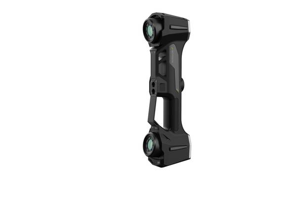
Selection should follow application requirements first. Teams evaluating scanner CAD CAM need to confirm that accuracy specifications align with part tolerances, that scan data exports cleanly into existing CAD/CAM software, and that any regulatory requirements — ASME, ISO, or sector-specific standards — are addressed before procurement.
INSVISION provides scanner CAD CAM systems designed around these industrial workflow considerations, with specifications available for direct evaluation against part-specific requirements.
- What Is 3D Scanning? Principles, Workflow, and Industrial Applications 3D scanning is a digital measurement technology that converts the surface geometry of physical objects into 3D data. This entry covers its working principles, core parameters, industrial use cases, common misconceptions, and related technical…
- What Is a 3D Scanner? Types, Parameters, and Selection Criteria A 3D scanner captures three-dimensional surface data from physical objects and converts geometry, dimensions, and features into digital data for inspection, reverse engineering, and modeling.
- What Is 3D Scanning Accuracy? Accuracy, Repeatability, and Resolution Explained 3D scanning accuracy describes how closely scan data matches an object's actual geometry and dimensions. It is assessed through local accuracy, volumetric accuracy, stitching accuracy, repeatability, and resolution.
- What Is Point Cloud Data? Point Clouds, Meshes, and CAD Models in 3D Scanning Point cloud data is an important raw data format in 3D scanning. It consists of discrete 3D coordinate points that describe object surface geometry and support inspection, reverse engineering, modeling, and archiving.
Hangzhou Insvision Technology Co., Ltd.
Address: Building 1, No. 1399 Liangmu Road, Yuhang District, Hangzhou, Zhejiang 311121, China
Copyright © Hangzhou Insvision Technology Co., Ltd. All rights reserved.
Copyright © Hangzhou Insvision Technology Co., Ltd. All rights reserved.