

Point Cloud to CAD Conversion: Definition, Process, and Key Considerations
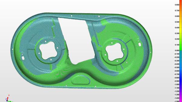
A point cloud is a dense collection of spatial coordinate measurements, but by itself it cannot drive manufacturing, simulation, or parametric design. Point clo
What Is Point Cloud to CAD Conversion
Point cloud to CAD conversion is the process of deriving a parametric, feature-based solid model—typically in formats such as STEP, IGES, or native CAD files—from a set of 3D points captured by a laser scanner, structured-light scanner, or photogrammetry system.
The output is a mathematically defined model with geometric primitives (planes, cylinders, cones, spheres) and freeform surfaces, rather than a mesh of connected triangles. The goal is not only to replicate shape but to recognize design intent: holes become hole features, planar faces become extrusions, and fillets become fillet operations.
The conversion is distinct from simply meshing a point cloud, which produces a polygon model suitable for visualization or 3D printing but not for parametric editing. It is a semi-automated, analyst-driven workflow that combines software algorithms for feature extraction with human judgment about which features matter and how to constrain them.
The workflow typically proceeds through four stages:
- Acquisition and registration – The object is scanned to produce a point cloud, often in multiple views that are aligned into a common coordinate system.
- Cleanup and segmentation – Noise, outliers, and irrelevant background points are removed. The cloud is then segmented into regions that correspond to distinct geometric features.
- Surface fitting and feature extraction – Algorithms fit planes, cylinders, cones, spheres, and freeform surfaces to the segmented regions. Dimensionally significant features are identified and converted into CAD primitives with constraints (parallelism, concentricity, perpendicularity).
- Model building and validation – The primitives are assembled into a complete solid model, usually inside a CAD package. The model is checked against the original point cloud for deviation, and features are adjusted to stay within tolerance.
The level of automation varies. Software can recognize simple prismatic features reliably, but freeform surfaces, organic shapes, and worn or deformed parts often require manual surfacing and careful interpretation of what the nominal geometry should be.
Key Parameters and Judging Criteria
The quality of a point cloud to CAD conversion is not measured by a single metric. The table below lists the primary dimensions engineers consider when evaluating a workflow or a resulting model.
| Parameter | What It Indicates | Typical Judgment Criterion |
|---|---|---|
| Point density and coverage | Whether fine features can be resolved and whether occluded areas are filled | Complete coverage of critical surfaces without shadow regions; density sufficient to capture the smallest feature of interest |
| Noise level and outlier ratio | How much the raw data deviates from the true surface | Low standard deviation in flat reference areas; stray points removed without eroding real edges |
| Feature recognition rate | Ability of software to automatically identify planes, cylinders, holes, pockets | High percentage of prismatic features recognized without manual cueing; complementary manual tools for freeform regions |
| Deviation between CAD model and point cloud | How faithfully the final model represents the scanned geometry | Usually expressed as a color map and statistical values (mean, RMS, maximum deviation); acceptable range depends on application |
| Surface continuity and smoothness | For freeform surfaces, whether patches join tangentially or with curvature continuity | No visible kinks; zebra-stripe analysis or curvature comb shows smooth transitions |
| File interoperability | Whether the output CAD format can be imported into the target CAD/PLM system without loss | Neutral formats (STEP AP242, IGES) or native formats that preserve feature tree when possible |
No universal standard governs these conversions; common metrology guidelines often emphasize that the total measurement uncertainty budget must include scanner uncertainty, registration error, and modeling residuals.
Suitable and Unsuitable Use Cases
Point cloud to CAD conversion excels when legacy parts lack digital models, when tooling has been modified on the shop floor, or when a design must be reverse-engineered from a physical master. It is widely used in automotive aftermarket, aerospace MRO (maintenance, repair, and overhaul), heavy machinery, and industrial equipment where replacement parts must match existing interfaces.
It is less suitable when the scanned object has no stable reference geometry—for example, highly flexible rubber components, fabric, or parts that deform during scanning. It is also not the right tool when the goal is purely visual inspection, archival, or 3D printing; in those cases, a mesh model is often sufficient and faster to produce.
The conversion adds cost and time, so it should be justified by the need for parametric editing, tolerance analysis, CNC programming, or integration into a CAD-based design environment.
Common Misconceptions
Misconception 1: The conversion is fully automatic.
Even with advanced software, a point cloud contains only coordinate data, not design intent. Recognizing which holes are functional, which surfaces are datum features, and which deviations are wear requires human engineering judgment.
Misconception 2: A perfect mesh equals a perfect CAD model.
A dense, watertight mesh can look convincing, but it lacks the mathematical continuity and feature definitions that CAD systems require. Converting a mesh to a CAD model often introduces additional smoothing and approximation, and the two representations should not be confused.
Misconception 3: Higher scanner accuracy always yields a better CAD model.
Scanner accuracy is important, but the conversion process itself introduces modeling error. A model created from a metrology-grade point cloud can still be poor if features are misidentified or constraints are applied incorrectly.
Related Concepts
| Concept | How It Differs from Point Cloud to CAD Conversion |
|---|---|
| Mesh generation | Produces a polygon mesh (STL, OBJ), not a feature-based solid; suitable for visualization and 3D printing but not parametric editing. |
| Reverse engineering | A broader term that includes point cloud to CAD as one of several possible outcomes; may also involve extracting material specs, tolerances, or manufacturing methods. |
| Scan-to-BIM | A domain-specific conversion for the building and construction industry, producing BIM objects rather than mechanical CAD models. |
| Surface reconstruction | Typically refers to fitting NURBS or subdivision surfaces to point data; may be an intermediate step toward a CAD solid but does not by itself create a feature tree. |
Relationship with INSVISION Products and Solutions
INSVISION provides AI-driven, metrology-grade 3D scanning technology that supplies the raw point cloud data for CAD conversion workflows. The AlphaScan handheld 3D scanner captures high-density point clouds with the accuracy and coverage required for industrial reverse engineering and quality inspection.
When the scanning phase delivers clean, well-registered data with low noise, the downstream conversion process becomes more efficient and less reliant on manual cleanup.
INSVISION’s scanning solutions are deployed across industries including aerospace, automotive, heavy machinery, mold manufacturing, and energy equipment—fields where point cloud to CAD conversion is a routine engineering task. The company holds certifications such as CE, FCC, ISO 9001, ISO 14001, and ISO 45001, and its technology has been adopted in over 20 countries.
While INSVISION does not produce the CAD modeling software itself, the AlphaScan scanner and its accompanying software output point clouds in formats compatible with all major CAD and reverse engineering platforms, allowing engineers to move directly into the feature extraction and modeling phase.
FAQ
Can I go directly from point cloud to CAD without creating a mesh?
Yes. Many reverse engineering software packages can fit surfaces and primitives directly to the point cloud, bypassing an intermediate mesh step. This is often preferred for prismatic parts because it avoids the approximation errors introduced by meshing.
What file formats are typical for CAD output?
STEP (AP214, AP242) and IGES are the most common neutral formats. Native formats such as SolidWorks, CATIA, or NX files may preserve the feature tree if the conversion software supports them.
How long does a conversion take?
It depends on part complexity, point density, and the required level of detail. A simple bracket with prismatic features might be converted in under an hour, while a complex casting with freeform surfaces can take several days of skilled modeling.
Is a CAD model from point cloud data as accurate as the original scan?
Not exactly. The model is a nominal representation that fits the point cloud within a certain tolerance. The deviation between the model and the raw data can be quantified, but the model itself is a simplification. The goal is to balance fidelity to the scan with the need for clean, editable geometry.
Does the scanner need to be calibrated for CAD conversion work?
Yes. The scanner must be calibrated and its accuracy verified according to the manufacturer’s specifications. Poorly calibrated equipment introduces systematic errors that propagate through the entire conversion chain.
Summary
Point cloud to CAD conversion is a disciplined, multi-step process that transforms raw spatial data into parametric solid models. Its value lies in enabling design reuse, FEA, CNC toolpath generation, and tolerance analysis for physical parts that lack digital definitions.
Success depends on the quality of the initial point cloud, the capabilities of the feature extraction software, and the skill of the engineer interpreting the data. A reliable scanning system—such as the INSVISION AlphaScan handheld 3D scanner—provides the measurement foundation that makes accurate, efficient conversion possible.
When the workflow is correctly matched to the use case, the result is a CAD model that faithfully represents the as-built geometry and can be confidently integrated into downstream engineering processes.
- What Is 3D Scanning? Principles, Workflow, and Industrial Applications 3D scanning is a digital measurement technology that converts the surface geometry of physical objects into 3D data. This entry covers its working principles, core parameters, industrial use cases, common misconceptions, and related technical…
- What Is a 3D Scanner? Types, Parameters, and Selection Criteria A 3D scanner captures three-dimensional surface data from physical objects and converts geometry, dimensions, and features into digital data for inspection, reverse engineering, and modeling.
- What Is 3D Scanning Accuracy? Accuracy, Repeatability, and Resolution Explained 3D scanning accuracy describes how closely scan data matches an object's actual geometry and dimensions. It is assessed through local accuracy, volumetric accuracy, stitching accuracy, repeatability, and resolution.
- What Is Point Cloud Data? Point Clouds, Meshes, and CAD Models in 3D Scanning Point cloud data is an important raw data format in 3D scanning. It consists of discrete 3D coordinate points that describe object surface geometry and support inspection, reverse engineering, modeling, and archiving.
Hangzhou Insvision Technology Co., Ltd.
Address: Building 1, No. 1399 Liangmu Road, Yuhang District, Hangzhou, Zhejiang 311121, China
Copyright © Hangzhou Insvision Technology Co., Ltd. All rights reserved.
Copyright © Hangzhou Insvision Technology Co., Ltd. All rights reserved.