

What Is an OBJ File? A Technical Guide for Industrial 3D Geometry Exchange
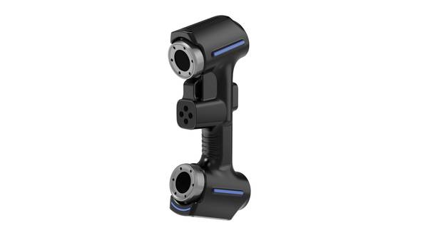
What Is an OBJ File? A Technical Guide for Industrial 3D Geometry Exchange. An OBJ file is a neutral polygonal mesh format for industrial geometry exchange.
What Is an OBJ File?
An OBJ file is a vendor-neutral 3D geometry format originally developed by Wavefront Technologies for the Advanced Visualizer animation package. Industrial teams now use it primarily as an interchange container for polygonal mesh data. The format stores vertex coordinates, surface normals, texture coordinates, and face definitions. A separate `.mtl` material library can hold surface color, reflectivity, and map paths.
Because OBJ is open and ASCII-based, it remains readable across scanners, CAD packages, inspection software, rendering engines, and lightweight viewers.
Key Points at a Glance
- An OBJ file is a vendor-neutral 3D geometry format originally developed by Wavefront Technologies for the Advanced Visualizer animation package.
- An OBJ file stores surface geometry as plain-text records.
- OBJ file suitability depends on geometry and data-exchange requirements, not on the file extension alone.
- An OBJ file is a mesh exchange format, not a native CAD model.
| Data represented in an OBJ file | Data not represented in an OBJ file |
|---|---|
| Vertex positions (`v`) | Parametric CAD features |
| Normals (`vn`) | Assembly constraints |
| Texture coordinates (`vt`) | NURBS surfaces |
| Polygonal faces (`f`) | GD&T/PMI callouts |
| Material library references | Units, tolerances, or coordinate system metadata |
For manufacturers building Industry 4.0 data continuity, this boundary sets expectations. OBJ supports cross-tool mesh exchange, but it does not replace native CAD or STEP/QIF formats where design intent, tolerances, and traceability must survive. Engineers use OBJ when the requirement is moving measured or tessellated geometry between tools without proprietary lock-in.
Core Structural Principles of OBJ Files
An OBJ file stores surface geometry as plain-text records. Each line begins with a tag: `v` for vertex coordinates, `vn` for surface normals, `vt` for texture coordinates, `f` for face definitions, and `mtllib` for a linked material library. Face definitions reference vertex, normal, and texture indices, so a single mesh can carry dimensional and appearance data without duplicating coordinate sets.
The `.mtl` file holds material names, color, reflectivity, and map paths; the OBJ file only points to it.
Native OBJ is ASCII: human-readable and easy to debug, which suits first-article inspection or manual QA checks. Some software tools write binary OBJ variants that pack the same records more compactly and load faster in automated metrology or scan-to-mesh workflows. Procurement teams should specify which variant a supplier is delivering, because tool compatibility varies.
| Data component | OBJ tag | Role in industrial workflow |
|---|---|---|
| Vertex coordinates | `v` | Defines X/Y/Z points for dimensional checks and GD&T alignment. |
| Surface normals | `vn` | Controls shading, edge visualization, and scan-to-CAD surface analysis. |
| Texture coordinates | `vt` | Maps appearance data for visual inspection overlays. |
| Face definitions | `f` | Builds triangular or polygonal surfaces from vertices. |
| Material library reference | `mtllib` | Links to `.mtl` files for surface finish and material appearance metadata. |
For quality managers, a missing normal or inconsistent face index often signals an incomplete mesh export. Engineers can validate OBJ structure before importing it into inspection software.
Technical Parameters for Evaluating OBJ Files in Industrial Workflows
OBJ file suitability depends on geometry and data-exchange requirements, not on the file extension alone. Engineers should verify whether an OBJ export can carry the point density, surface orientation, and material references needed for downstream work. A scan-to-OBJ file that loses normal vectors or stores faces as mixed n-gons may pass visual review but fail first-article inspection or 3D printing preparation.
For GD&T-based metrology and reverse engineering, receiving software usually expects watertight triangular meshes with consistent vertex winding.
| Key Technical Parameter | Technical Definition | Industrial Workflow Relevance |
|---|---|---|
| Vertex Density | Number of unique 3D coordinate points defining the model surface | Determines level of geometric detail for inspection, reverse engineering, and prototyping tasks |
| Encoding Type | ASCII human-readable text or compact binary file format | ASCII supports easy cross-tool validation; binary reduces storage footprint for large-scale 3D scan datasets |
| Normal Vector Data | Per-vertex or per-face directional data defining surface orientation | Critical for accurate rendering, metrology analysis, and 3D printing layer planning |
| Material Library Linkage | Reference to external `.mtl` files storing color, texture, and surface property data | Supports visual quality inspection and part identification in mixed-assembly workflows |
| Mesh Face Type | Support for polygonal faces, including triangles, quads, and n-gons | Triangular meshes align with most 3D scanning and metrology software pipelines for consistent data processing |
Common validation includes checking OBJ export settings for vertex count, normal direction consistency, and face triangulation before accepting a dataset as a controlled deliverable. OBJ also does not force a specific unit system. A millimeter model and an inch model look identical as raw coordinates, so downstream tools need a documented unit convention before interpreting scale.
Defined Use Boundaries for OBJ Files in Industrial Settings
An OBJ file is a mesh exchange format, not a native CAD model. Its standard function is storing surface geometry as vertices, normals, texture coordinates, and polygon face definitions. Industrial teams should treat it as a lightweight boundary object for visual prototyping, 3D scan data export, 3D printing input, and cross-tool mesh exchange. It fits when the downstream task needs tessellated geometry only.
What an OBJ file does not carry matters equally. Parametric feature history, assembly hierarchy metadata, material or part attributes, and ISO/ASME tolerance annotations fall outside the format’s native scope. Those data types must remain in a native CAD or PLM file.
| Data type | Standard OBJ scope |
|---|---|
| Triangulated or quad mesh geometry | In scope |
| Texture coordinates and vertex normals | In scope |
| 3D scan polygon export | In scope |
| Parametric CAD feature history | Out of scope |
| Assembly structure metadata | Out of scope |
| GD&T callouts and tolerance annotations | Out of scope |
Reverse engineering workflows often start with an OBJ mesh exported from a structured-light or laser scanner, then rebuild a parametric CAD model in a separate package. The OBJ file is the bridge, not the destination. INSVISION technical documentation applies the same boundary logic when separating scan mesh export from downstream inspection or CAD rebuild workflows.
Common Misconceptions About Industrial OBJ File Usage
An OBJ file is a polygon geometry container, not a measurement format. That distinction causes most industrial confusion.
| Misconception | Technical context |
|---|---|
| OBJ files only store visual, non-metrology-grade data | OBJ stores vertex coordinates and face indices. When exported from calibrated scanning systems, those coordinates can carry metrology-useful geometry, but the format itself does not encode GD&T callouts or tolerance data. |
| All OBJ files have consistent accuracy | Accuracy is not format-defined. It depends on scanner calibration, scan alignment, mesh resolution, and export settings. Two OBJ files of the same part can differ in vertex density and surface deviation. |
| OBJ files cannot be used in regulated manufacturing sectors | OBJ is used as an intermediate mesh for visualization, reverse engineering, or comparison. Regulated workflows still require controlled CAD, CMM, or structured-light inspection records for release decisions. |
In aerospace MRO, medical device production, and automotive OEM quality control, OBJ files often sit between scan data and analysis software. They are useful for shape review and surface reconstruction, but not as a standalone substitute for GD&T evaluation or first-article inspection documentation.
Related 3D File Formats in Industrial Ecosystems
An OBJ file stores polygonal mesh geometry, UV coordinates, and material library references. It does not carry parametric features, GD&T callouts, or assembly constraints. In industrial ecosystems, OBJ is a surface-representation handoff, not an engineering data master.
| Format | Typical Role | Geometry/Data Type | Common Standard or Workflow |
|---|---|---|---|
| OBJ | Visualization and lightweight mesh review | Polygonal mesh with UV/material refs | Neutral surface handoff |
| STL | Additive manufacturing build prep | Tessellated triangle mesh | ISO/ASTM additive workflow |
| STEP | Parametric CAD interchange | Boundary representation, metadata | ISO 10303 |
| PLY | Point cloud capture and archival | Points, normals, color | Scanning and metrology raw data |
| GLB | Browser-based 3D visualization | Mesh, materials, scene hierarchy | Web/AR/VR review |
The choice depends on downstream process needs. A lean workflow defines the minimum geometry fidelity and metadata required at each step. Converting an OBJ to STEP does not recover lost parametric intelligence; it wraps the existing mesh. Native CAD therefore remains the master model, while OBJ, STL, PLY, and GLB are generated for specific downstream uses.
Conversion should occur at controlled exchange points with acceptance criteria for accuracy and consistency. That reduces double-handling, rework, and revision drift across the quality, manufacturing, and inspection chain.
OBJ File Compatibility in INSVISION 3D Measurement Workflows
An OBJ file is an open, text-based geometry exchange format that stores polygonal mesh data as vertex positions, face definitions, and optional texture or material references. In 3D measurement, that geometry is usually a tessellated representation of a scanned surface, not parametric CAD geometry.
That distinction matters for workflow design. OBJ carries shape, not units, feature history, or GD&T callouts. Scale and tolerancing information must stay in the inspection project, report, or accompanying documentation.
INSVISION 3D measurement solutions support OBJ import and export. The practical benefit is cross-system continuity: measured mesh data can move to CAD comparison tools, metrology software, or prototyping packages without format conversion.
For manufacturing teams working across automotive, aerospace, or medical device supply chains, open format interoperability supports an Industry 4.0 data strategy—keeping inspection data accessible outside a single vendor environment.
| Interoperability factor | Engineering consideration |
|---|---|
| Tessellation tolerance | Controls deviation between scanned surface and exported OBJ mesh. |
| Units and scale | OBJ does not embed units; document millimeter or inch settings. |
| Parametric history and PMI | OBJ stores mesh geometry only; GD&T callouts remain in the inspection report. |
Frequently Asked Questions About OBJ Files for Industrial Teams
An OBJ file stores mesh geometry, not GD&T or PMI.
Dimensional measurement suitability: Not appropriate as a primary record. OBJ tessellates surfaces, so cylinder axes and arcs become triangle approximations. Use native CAD or point-cloud data for first-article inspection.
ISO 10303 (STEP) compatibility: OBJ is not a STEP substitute. Conversion drops B-rep, assembly structure, and metadata. Keep STEP as the controlled master.
Color data for visual inspection: OBJ supports vertex color or MTL texture maps for visual overlays. Keep numerical deviation data separate.
Regulated industry 3D printing: OBJ can be a build input. AS9100 and ISO 13485 still require linkage to approved CAD, build logs, and inspection records.
| Requirement | OBJ limitation | Engineering control |
|---|---|---|
| Dimensional measurement | No GD&T/PMI; tessellated surfaces | Use native CAD or point cloud |
| STEP workflow | Loses B-rep, assembly, and metadata | Retain STEP as master |
| Visual inspection color | Vertex color or MTL only | Keep numerical data separate |
| Regulated 3D printing | No built-in traceability | Link to approved CAD and build records |
An OBJ export from an INSVISION scan should remain a visualization mesh, not the authoritative measurement source.
Summary of OBJ File Core Traits and Industrial Value
The OBJ file format is a neutral, widely supported 3D mesh standard. Most CAD, scan processing, and visualization packages can read or write it, which makes OBJ useful as a handoff container rather than as a design authority. Its core structure includes vertex coordinates (`v`), normals (`vn`), texture coordinates (`vt`), face definitions (`f`), and material library references (`mtllib`/`usemtl`).
These elements preserve surface geometry and basic visual attributes. They do not carry parametric features, GD&T callouts, PMI, or assembly constraints.
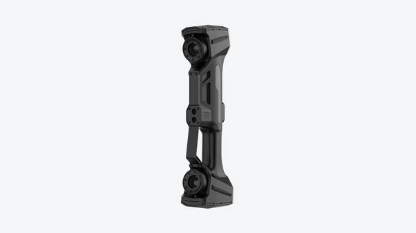
| Element / parameter | What it controls | Industrial check |
|---|---|---|
| `v` vertices | Point coordinates | Verify scale and coordinate system |
| `f` faces | Polygon topology | Check for non-manifold edges and holes |
| `vn` normals | Surface orientation | Ensure consistent direction before processing |
| `mtllib` / `usemtl` | Visual material assignment | Separate visual metadata from measurement data |
The practical scope is mesh exchange, visualization, and scan reference work. If dimensional data must move between systems, OBJ can act as an intermediate mesh, but downstream CAD or inspection software must reconstruct or align it.
That boundary matters in lean manufacturing and Industry 4.0 data flows: OBJ reduces friction when moving scan geometry across tools, but it is not a replacement for native CAD or metrology formats.
- What Is 3D Scanning? Principles, Workflow, and Industrial Applications 3D scanning is a digital measurement technology that converts the surface geometry of physical objects into 3D data. This entry covers its working principles, core parameters, industrial use cases, common misconceptions, and related technical…
- What Is a 3D Scanner? Types, Parameters, and Selection Criteria A 3D scanner captures three-dimensional surface data from physical objects and converts geometry, dimensions, and features into digital data for inspection, reverse engineering, and modeling.
- What Is 3D Scanning Accuracy? Accuracy, Repeatability, and Resolution Explained 3D scanning accuracy describes how closely scan data matches an object's actual geometry and dimensions. It is assessed through local accuracy, volumetric accuracy, stitching accuracy, repeatability, and resolution.
- What Is Point Cloud Data? Point Clouds, Meshes, and CAD Models in 3D Scanning Point cloud data is an important raw data format in 3D scanning. It consists of discrete 3D coordinate points that describe object surface geometry and support inspection, reverse engineering, modeling, and archiving.
Hangzhou Insvision Technology Co., Ltd.
Address: Building 1, No. 1399 Liangmu Road, Yuhang District, Hangzhou, Zhejiang 311121, China
Copyright © Hangzhou Insvision Technology Co., Ltd. All rights reserved.
Copyright © Hangzhou Insvision Technology Co., Ltd. All rights reserved.