

Multi-View Alignment in 3D Scanning
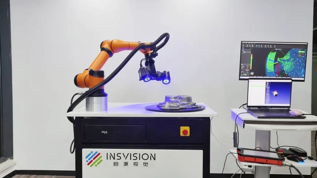
Multi-view alignment in 3D scanning is the core data processing workflow that registers, spatially aligns, and prepares for merging multiple partial 3D point clouds or mesh captures—each collected from a distinct vantage point relative to a target object or scene—into a single, geometrically consistent 3D dataset.
Definition
Multi-view alignment in 3D scanning is the core data processing workflow that registers, spatially aligns, and prepares for merging multiple partial 3D point clouds or mesh captures—each collected from a distinct vantage point relative to a target object or scene—into a single, geometrically consistent 3D dataset. The process resolves blind spots and coverage gaps that occur when a target’s full geometry cannot be captured in a single scan, and is a standard intermediate step in industrial 3D reconstruction, inspection, and reverse engineering workflows.
How It Works
Multi-view alignment follows a standardized sequence of steps, which may be executed manually, semi-automatically, or fully automatically depending on hardware and software configurations:
- Scan Capture: Multiple partial scans are collected from different positions and angles around the target, with intentional overlap between adjacent scans to provide common reference data. Some workflows use external optical tracking systems to record scanner position in real time during capture, eliminating the need for post-capture alignment.
- Reference Feature Extraction: The system identifies shared reference data across overlapping scans, which may include natural surface features (edges, curves, texture patterns), artificial fiducial markers placed on or near the target, or geometric primitives (planes, cylinders, holes) inherent to the part.
- Coarse Alignment: Initial registration of all scans into a single common coordinate system, using high-level reference features to resolve large positional and rotational offsets between views. Common algorithms for this step include RANdom SAmple Consensus (RANSAC) and fiducial marker matching.
- Fine Alignment: Iterative refinement of the initial alignment to minimize spatial deviation between corresponding points in overlapping scan regions. The Iterative Closest Point (ICP) algorithm and its AI-enhanced variants are the most widely used tools for this step.
- Validation and Merging: The aligned dataset is checked for residual alignment error, redundant overlapping data is removed, and the individual scans are fused into a single continuous 3D model for downstream use.
Key Parameters and Criteria
The performance of multi-view alignment workflows is evaluated using measurable, application-specific parameters that directly impact the accuracy and utility of the final 3D model. Core evaluation criteria are outlined in the table below:
| Parameter | Meaning | Judgment Method |
|---|---|---|
| Alignment RMS Error | The root mean square of distance deviations between corresponding points in overlapping regions of aligned scans, the primary metric for alignment precision. | Calculated via scanning software by comparing matched fiducial markers, common surface points, or reference CAD data across aligned datasets; lower RMS values indicate higher alignment accuracy. |
| Scan Overlap Ratio | The percentage of shared geometric content (by point count or surface area) between two adjacent scans, required to enable reliable feature matching. | Measured as the proportion of a scan’s surface area that appears in a neighboring view; required minimum values vary by object complexity, feature density, and alignment algorithm. |
| Registration Degrees of Freedom (DoF) | The number of independent positional and rotational adjustments applied to align a scan to the common coordinate system (standard 3D alignment uses 6 DoF: X, Y, Z translation, roll, pitch, yaw). | Verified via software alignment logs or coordinate system deviation reports; full 6 DoF alignment is required for freeform object scanning, while lower DoF may be sufficient for flat or prismatic parts. |
| Alignment Processing Latency | The total time required to complete full alignment of all captured scans into a single registered dataset. | Measured from the end of scan capture to the output of a fully aligned point cloud or mesh; varies with scan resolution, number of views, and processing hardware/software capabilities. |
Suitable and Unsuitable Scenarios
Suitable Scenarios
- Complex freeform industrial parts (e.g., turbine blades, automotive body panels, injection molds) with undercuts, recessed features, or hidden surfaces that cannot be fully captured in a single scan view.
- Large-format workpieces (e.g., aircraft fuselage sections, heavy machinery frames, wind turbine components) that exceed the single-scan field of view of standard scanning hardware.
- High-precision quality inspection workflows requiring full 3D coverage for dimensional tolerance analysis, defect detection, or first-article inspection.
- Automated inline scanning workflows where multiple fixed scanners or robot-mounted scanners capture discrete sections of parts moving along a production line.
Unsuitable Scenarios
- Uniform, featureless flat objects with no distinct surface geometry or fiducial markers to serve as alignment references, unless paired with external position tracking hardware.
- Highly deformable objects that change shape between scan captures, as shifting geometry eliminates the consistent overlapping features required for accurate alignment.
- Ultra-small micro-scale parts where the full geometry fits within a single scan’s field of view, making multi-view alignment redundant and a potential source of avoidable measurement error.
Common Misconceptions
- Misconception: Adding more scan views always improves alignment accuracy.
Correction: Additional views with insufficient overlap, high noise levels, or no unique shared features can increase alignment error and processing time. Optimal view count depends on object size, complexity, and the required overlap ratio for the selected alignment method.
- Misconception: Markerless alignment is inherently more accurate than marker-based alignment.
Correction: Marker-based alignment delivers consistent, traceable results for low-feature, high-reflectivity, or transparent surfaces, while markerless alignment performs best on high-feature, matte surfaces. Accuracy is determined by use case fit, not the alignment method alone.
- Misconception: Alignment error can be completely eliminated.
Correction: All multi-view alignment processes introduce a small, measurable level of residual error, driven by scan noise, feature ambiguity, and algorithm limitations. Workflows are designed to reduce error to application-specific acceptable thresholds, not eliminate it entirely.
- Misconception: Multi-view alignment always requires manual post-processing.
Correction: Modern industrial scanning software supports fully automated alignment for high-feature parts, while optical tracking systems enable real-time alignment during scan capture, eliminating the need for manual post-processing steps for many use cases.
Related Concepts
- Point Cloud Registration: The broader category of computational algorithms used to align multiple 3D point datasets, of which multi-view alignment is a targeted application for 3D scanning workflows.
- Iterative Closest Point (ICP): A widely used iterative algorithm for fine alignment of 3D point clouds, which minimizes the distance between corresponding point pairs in overlapping datasets.
- Fiducial Markers: High-contrast, dimensionally stable artificial targets placed on or near a scan object to provide unambiguous, traceable reference points for alignment.
- Optical Tracking: A hardware-based positioning system that records the 3D position and orientation of a scanner in real time, enabling live multi-view alignment without post-capture processing.
- 3D Reconstruction: The end-to-end process of generating a complete, usable 3D model from raw scan data, of which multi-view alignment is a core intermediate step.
FAQ
How much overlap is required between adjacent scans for reliable multi-view alignment?
The minimum required overlap ratio varies by object type, alignment method, and hardware configuration. For markerless alignment of high-feature objects, a 20–30% surface overlap between adjacent scans is typical. For low-feature objects or marker-based workflows, lower overlap may be sufficient if distinct fiducial markers are present in shared scan regions.
Can multi-view alignment be performed on scans captured with different types of 3D scanners?
Yes, provided the scans share identifiable common features, fiducial markers, or a common coordinate reference. Cross-hardware alignment may require additional calibration to account for differences in scan resolution, measurement accuracy, and noise levels between devices.
What is the difference between coarse and fine multi-view alignment?
Coarse alignment is the initial step that resolves large positional and rotational offsets between scans to bring them into approximate alignment within a common coordinate system, using high-level features or fiducial markers. Fine alignment follows, using iterative algorithms to minimize point-to-point deviation between overlapping scans to achieve the final target precision.
How do AI-enhanced algorithms improve multi-view alignment performance?
AI-enhanced alignment algorithms can improve feature detection accuracy on low-contrast, high-noise, or partially obscured scan regions, reduce processing time for large multi-scan datasets, and minimize the need for manual intervention for complex freeform parts, compared to traditional rule-based alignment algorithms.
Summary
Multi-view alignment is a foundational process in industrial 3D scanning that enables the creation of complete, geometrically consistent 3D models by merging multiple partial scans captured from distinct vantage points. Its performance is evaluated via standardized, measurable parameters including alignment RMS error, scan overlap ratio, and processing latency, with suitability varying based on object complexity, size, and application requirements. Correct implementation of multi-view alignment workflows supports a wide range of industrial use cases including dimensional inspection, reverse engineering, and automated manufacturing quality control.
- What Is 3D Scanning? Principles, Workflow, and Industrial Applications 3D scanning is a digital measurement technology that converts the surface geometry of physical objects into 3D data. This entry covers its working principles, core parameters, industrial use cases, common misconceptions, and related technical…
- What Is a 3D Scanner? Types, Parameters, and Selection Criteria A 3D scanner captures three-dimensional surface data from physical objects and converts geometry, dimensions, and features into digital data for inspection, reverse engineering, and modeling.
- What Is 3D Scanning Accuracy? Accuracy, Repeatability, and Resolution Explained 3D scanning accuracy describes how closely scan data matches an object's actual geometry and dimensions. It is assessed through local accuracy, volumetric accuracy, stitching accuracy, repeatability, and resolution.
- What Is Point Cloud Data? Point Clouds, Meshes, and CAD Models in 3D Scanning Point cloud data is an important raw data format in 3D scanning. It consists of discrete 3D coordinate points that describe object surface geometry and support inspection, reverse engineering, modeling, and archiving.
Hangzhou Insvision Technology Co., Ltd.
Address: Building 1, No. 1399 Liangmu Road, Yuhang District, Hangzhou, Zhejiang 311121, China
Copyright © Hangzhou Insvision Technology Co., Ltd. All rights reserved.
Copyright © Hangzhou Insvision Technology Co., Ltd. All rights reserved.