

Large Part 3D Scanning Fundamentals, Key Parameters and Use Boundaries
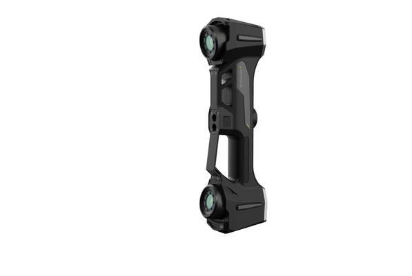
large part 3D scanning: Meta description: Large part 3D scanning fundamentals: measurement principles, key parameters, application boundaries, common.
Meta description: Large part 3D scanning fundamentals: measurement principles, key parameters, application boundaries, common misconceptions, and ISO/ASME inspection integration.
What Large Part 3D Scanning Means
Large part 3D scanning is a non-contact metrology method for capturing complete surface geometry from parts and assemblies whose size, weight, or access constraints exceed the practical work envelope of standard small-part scanning systems. The definition is tied to application fit rather than a fixed dimensional cutoff.
A full automotive body, an aerospace fuselage section, and a wind turbine blade root are considered large because they cannot be measured completely in a single bench setup without losing volumetric control.
Key Points at a Glance
- Large part 3D scanning is a non-contact metrology method for capturing complete surface geometry from parts and assemblies whose size, weight, o…
- Large part 3D scanning converts physical surfaces into coordinate data through four main optical measurement principles.
- Large part 3D scanning should be evaluated through measurable engineering parameters, not demo image quality.
- Large part 3D scanning is most applicable when a part is rigid enough to remain stable during capture and large enough that a fixed bridge or ga…
The core purpose spans precision inspection against GD&T callouts, reverse engineering of legacy components without CAD data, and creation of digital assets for tooling, simulation, or maintenance planning. Large part workflows typically combine laser or structured light scanning with photogrammetry targets or tracker references to keep global accuracy stable.
ISO 10360 provides the acceptance and reverification framework for coordinate measuring systems, while large-scale measurement also requires checks for thermal drift, target placement, and multi-setup alignment.
| Classification factor | Typical requirement in large-part scanning |
|---|---|
| Part handling | Minimal reorientation; in-place measurement |
| Accuracy control | Global volumetric accuracy tied to reference targets |
| Data output | Full-surface mesh aligned to assembly coordinates |
| Main constraint | Scale and thermal stability more than local resolution |
Metrology providers such as INSVISION frame large part 3D scanning as a system-level capability rather than a single scanner specification.
How Large Part 3D Scanning Works
Large part 3D scanning converts physical surfaces into coordinate data through four main optical measurement principles. The suitable method depends on part size, surface finish, and the tolerance requirements shown on the drawing.
| Method | How it captures point cloud data | Large-part behavior |
|---|---|---|
| Laser triangulation | A laser line or spot reflects into an offset camera; triangulation returns range from the known geometry. | High local accuracy; requires many overlapping passes. |
| Structured light scanning | A projector casts coded light patterns and cameras detect surface distortion to reconstruct shape. | Dense data capture; sensitive to lighting and surface condition. |
| Photogrammetry | Overlapping images are matched through feature correspondence to solve 3D coordinates. | Scales to very large objects; often anchors global reference networks. |
| Time-of-flight scanning | Measures light pulse or phase return time per pixel. | Long range; lower point density; suited to large structures. |
For parts over a few meters, alignment contributes more to final accuracy than raw scan resolution. Individual scans are tied together with reference markers placed on or around the part. A global control network—established by photogrammetry or a laser tracker—locks all local scans into one coordinate system and limits accumulated error.
The aligned point cloud can then be checked against CAD using GD&T callouts such as surface profile or positional tolerance.
In an Industry 4.0 digital thread, that aligned point cloud feeds digital twin geometry, first-article inspection records, and quality management systems. The engineering value comes from traceable scan data: coordinate system, part serialization, and measurement metadata travel with the point cloud instead of remaining an isolated inspection file.
Parameters That Define Performance
Large part 3D scanning should be evaluated through measurable engineering parameters, not demo image quality. These parameters act as pass/fail criteria tied to part size, tolerance class, and inspection workflow.
| Key parameter | Technical definition | Industrial relevance |
|---|---|---|
| Scanning volume | Single-setup measurement envelope. | Determines coverage of large fabrications without excessive repositioning. |
| Measurement accuracy | Deviation from traceable reference values. | Supports GD&T callouts and first-article inspection to ISO/ASME tolerances. |
| Point cloud density | Points per unit area or minimum spacing. | Resolves small radii, holes, and edge transitions on large parts. |
| Scan acquisition speed | Area or points captured per second. | Sets throughput on large parts and reduces CMM backlog. |
| Environmental operating tolerance | Allowable temperature, vibration, and light limits. | Confirms shop-floor or outdoor use without accuracy loss. |
| Data output format compatibility | Native export to neutral formats such as STL, PLY, or XYZ. | Avoids conversion bottlenecks in reverse engineering and digital twin workflows. |
These parameters interact. High point density adds little value if the scanner cannot hold accuracy under shop-floor vibration, and fast acquisition is wasted if the output format breaks the inspection software chain.
Where Large Part 3D Scanning Fits
Large part 3D scanning is most applicable when a part is rigid enough to remain stable during capture and large enough that a fixed bridge or gantry CMM requires repeated setups or cannot reach critical surfaces. In automotive OEM work, that includes full vehicle body gap and flush inspection and large body-in-white tooling validation.
Aerospace MRO uses the method for fuselage component inspection and reverse engineering of legacy replacement parts where original drawings are incomplete. Renewable energy applies it to wind turbine blade geometric inspection. Heavy equipment plants inspect large castings and forgings near production flow.
Point clouds are compared with CAD nominal geometry using ASME Y14.5 surface profile, position, and datum reference frame callouts. The lean benefit is less part movement and faster first-article inspection feedback, because the scanner moves to the part instead of moving the part to a fixed machine.
| Industrial sector | Typical large-part target | ASME Y14.5 focus | Lean objective |
|---|---|---|---|
| Automotive OEM | Full vehicle body, body-in-white tooling | Surface profile, gap/flush, position | Fewer setups; faster tool correction |
| Aerospace MRO | Fuselage components, legacy parts | Surface profile, hole position | Reverse engineering without disassembly |
| Renewable energy | Wind turbine blades | Surface profile, chord/twist deviation | Inspect near production flow |
| Heavy equipment | Large castings, forgings | Surface profile, datum reference frames | Reduce part handling |
This makes the method suited to non-contact measurement of large, rigid assemblies where fixed CMM reach is limited.
Misconceptions That Skew Evaluation
A recurring misconception is that every large part 3D scanning project requires extensive surface pre-treatment. The actual need for spraying or matting depends on the optical principle and the material. Many laser-based systems acquire machined, cast, or dark surfaces without full coating. Transparent, glossy, or highly reflective parts may still need a thin developer, but pre-treatment is not a universal requirement.
| Misconception | Technical clarification |
|---|---|
| All materials need full surface pre-treatment before large part 3D scanning. | Pre-treatment depends on surface reflectivity, translucency, and scanner wavelength. Many metals and castings scan without coating. |
| Accuracy is uniform across the entire maximum scan volume. | Volumetric accuracy can vary with distance and position. Reference length checks at multiple locations are standard for ISO/ASME first-article inspection. |
| Large part 3D scanning is limited to climate-controlled labs. | Factory cells, MRO hangars, and outdoor energy sites are common. Thermal stability, rigid setup, and vibration control matter more than a cleanroom. |
For process decisions, the practical criteria are material type, required GD&T callouts, ambient temperature range, and part movement during measurement. These factors, not the maximum advertised volume alone, determine system fit in Western manufacturing environments.
Integration with Digital Manufacturing
Large part 3D scanning does not work as a stand-alone inspection step. It produces dense coordinate data that feeds adjacent manufacturing and quality systems.
| Concept | What large part 3D scanning enables | Typical system connection |
|---|---|---|
| Digital twin development | As-built mesh or point cloud compared to nominal CAD | PLM, CAD, or digital twin software |
| First article inspection (FAI) | Full surface deviation reporting against GD&T callouts | AS9102/ISO 9001 quality records |
| Reverse engineering for MRO | Capture worn or undocumented parts as CAD-ready geometry | CAD reconstruction tools |
| Statistical process control (SPC) | Trending of critical dimensions over serial production | SPC software or QMS database |
In practice, scan output—STL, CSV, or native inspection formats—must move into these systems without manual re-entry. Western manufacturing teams usually link scan results to part number, revision, and inspection plan inside the QMS. That keeps audit records traceable and allows CAD overlays for root cause analysis.
Used this way, large part 3D scanning supports lean material traceability and Industry 4.0 data loops without replacing existing quality gates. It adds dimensional visibility where traditional hard gauges miss surface variation.
INSVISION’s Role in Large Part 3D Scanning
Large part 3D scanning is used when dimensional controls must extend across surfaces, weldments, and assembly features too large for conventional CMM work envelopes. In heavy manufacturing, acceptance criteria are typically tied to ISO or ASME metrology standards, with attention to volumetric accuracy, datum repeatability, and thermal compensation.
INSVISION develops application-specific scanning configurations for large components in aerospace, automotive, and renewable energy. The work focuses on measurement challenges such as surface variation on welded structures, edge definition on composite panels, and scale-related error on long weldments.
| Application area | Typical large-part scanning requirement | Main technical concern |
|---|---|---|
| Aerospace skins and panels | Full-surface measurement against GD&T profile callouts | Edge definition, thermal drift |
| Automotive body-in-white | Check gap, flush, and springback over large assemblies | Datum stability, repeatable alignment |
| Renewable energy structures | Verify machined features and weld geometry | Volumetric accuracy over long distances |
INSVISION’s systems align with ISO and ASME metrology practices and are intended for first-article inspection and in-process dimensional checks. Application fit, rather than brand comparison, remains the technical focus.
Frequently Asked Questions About Large Part 3D Scanning
What types of materials are compatible with large part 3D scanning?
Material compatibility in large part 3D scanning is often misunderstood. Metals, composites, plastics, ceramics, and tooling board can all be measured. The real constraints are surface reflectivity and finish. Shiny, transparent, or very dark surfaces usually need a temporary matte coating or reference targets to capture clean data.
Can scan data be integrated directly with existing CAD and GD&T inspection software?
Yes, in most workflows. Systems typically export mesh or point cloud data in STL, PLY, or ASCII formats. Engineering teams import those files into standard CAD and inspection packages, then align the scan to nominal geometry. Profile, flatness, runout, and position callouts can then be checked. Some cleanup or decimation is often required for very large datasets.
What calibration processes are standard for large part 3D scanning systems?
| Verification element | Typical method | What it checks |
|---|---|---|
| Length accuracy | Certified scale bar or gauge block | Error over a known distance |
| Volume stability | Reference sphere plate or target array | Error distribution across working volume |
| Tracking alignment | Coded markers or photogrammetry points | Repeatability on long parts |
| Thermal drift | Warm-up and temperature check | Session-to-session stability |
Is large part 3D scanning suitable for FAI in aerospace and medical device manufacturing?
It can support FAI work, but it is not a universal replacement for probing. Full-surface scanning works well for contour profiles, radii, and large-area deviation maps. Tight datum features, sealing faces, and small threaded holes may still require tactile CMM checks. Many aerospace and medical quality groups use scanning as a complement during first-article inspection.
Summary of Core Large Part 3D Scanning Concepts
| Parameter | What it affects |
|---|---|
| Volumetric accuracy | Deviation from true geometry over the full scan envelope |
| Standoff / depth of field | Tolerance to surface variation and access constraints |
| Resolution / point spacing | Smallest feature that can be captured reliably |
| Scan speed | Cycle time and point-cloud completeness |
| Environmental stability | Behavior under vibration, temperature shifts, and lighting changes |
Primary uses include first-article inspection, tooling verification, reverse engineering of legacy parts, and distortion analysis in aerospace MRO and energy components. Scan data feeds CAD comparison, GD&T callout validation, FAI reporting, and digital twin updates.
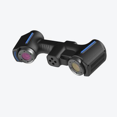
Implementation depends on matching scanner capability to part size, tolerance class, and environment. A system that works for a large composite layup mold may be unsuitable for a cast housing with tight bores. No single scanner specification predicts success across all large part applications.
- What Is 3D Scanning? Principles, Workflow, and Industrial Applications 3D scanning is a digital measurement technology that converts the surface geometry of physical objects into 3D data. This entry covers its working principles, core parameters, industrial use cases, common misconceptions, and related technical…
- What Is a 3D Scanner? Types, Parameters, and Selection Criteria A 3D scanner captures three-dimensional surface data from physical objects and converts geometry, dimensions, and features into digital data for inspection, reverse engineering, and modeling.
- What Is 3D Scanning Accuracy? Accuracy, Repeatability, and Resolution Explained 3D scanning accuracy describes how closely scan data matches an object's actual geometry and dimensions. It is assessed through local accuracy, volumetric accuracy, stitching accuracy, repeatability, and resolution.
- What Is Point Cloud Data? Point Clouds, Meshes, and CAD Models in 3D Scanning Point cloud data is an important raw data format in 3D scanning. It consists of discrete 3D coordinate points that describe object surface geometry and support inspection, reverse engineering, modeling, and archiving.
Hangzhou Insvision Technology Co., Ltd.
Address: Building 1, No. 1399 Liangmu Road, Yuhang District, Hangzhou, Zhejiang 311121, China
Copyright © Hangzhou Insvision Technology Co., Ltd. All rights reserved.
Copyright © Hangzhou Insvision Technology Co., Ltd. All rights reserved.