

How Blue Light and Object Size Shape the Limits of 3D Scanning
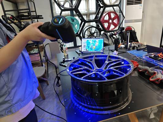
A measurement system is only as trustworthy as the conditions it can handle. In industrial 3D scanning, two variables often decide whether a scan delivers usabl
What Blue Light 3D Scanning Actually Means
Blue light 3D scanning refers to structured light systems that project a narrowband blue LED pattern, typically in the 450 nm range, onto a surface. Cameras capture the deformation of that pattern from known angles, and software reconstructs the 3D geometry through triangulation. The shift to blue was not arbitrary.
Shorter wavelengths reduce the influence of ambient light, especially in factory environments where overhead fluorescent or incandescent sources can wash out a projected pattern. Because blue light scatters less than red or white light, the fringe edges remain sharper. That sharpness translates directly into lower measurement noise on reflective or semi-transparent materials.
Deployment Validation Checklist
| Focus Area | Decision Point | Deployment Note |
|---|---|---|
| Target part | Check size, surface condition, and key tolerances against the scan task | Run a full trial scan on a representative part |
| Data workflow | Verify point cloud, deviation map, and quality-report handoff | Confirm export formats and review ownership in advance |
| Shop-floor use | Review training, calibration, lighting, and working space | Keep the validation record as a repeatable inspection reference |
Scenario Snapshot
A practical way to read the article is through this scenario:
- What Blue Light 3D Scanning Actually Means: Blue light 3D scanning refers to structured light systems that project a narrowband blue LED pattern, typically in…
- How Lighting and Object Size Interact in Practice: Lighting and object size are often treated as separate concerns: lighting as a surface preparation problem, size a…
- Application Boundaries for Large-Format Scanning: A large-format handheld 3D scanner like the AlphaVista from INSVISION is designed to push these boundaries further.
The engineering trade-off is depth of field. Higher-frequency light sources produce tighter focal planes, which means the scanner’s working distance and measurement volume are inherently linked to the optics. A system designed for high-resolution detail on a palm-sized bracket will struggle to maintain that same point density across a meter-wide automotive panel. This is not a defect of the technology;
it is a physical constraint of triangulation-based optical metrology.
How Lighting and Object Size Interact in Practice
Lighting and object size are often treated as separate concerns: lighting as a surface preparation problem, size as a scanning volume problem. In reality, they form a single boundary condition. As an object grows, the scanner must operate at a greater standoff distance to capture the full field of view.
That distance reduces the effective intensity of the projected pattern and widens the angle of incidence at the edges of the frame. The result is a drop in signal-to-noise ratio, particularly on dark or matte surfaces that already absorb a significant portion of the blue light energy.
Material response adds another layer. Large castings, composite molds, and sheet metal assemblies rarely present a uniform surface. A single scan session may move from a machined aluminum flange (highly reflective) to a sand-cast iron surface (diffuse and absorptive) within the same field of view.
Blue light scanners handle this variance better than white light or laser alternatives because the narrowband source can be tuned to a specific exposure range, but the operator still faces a practical limit. If the part is too large for a single exposure cycle, the system must rely on stitching multiple scans together.
Marker-based alignment or photogrammetry targets become essential, and the quality of that global registration often matters more than the per-scan accuracy. INSVISION addresses this with its SMARPARA Q software, which supports multi-source data alignment and deviation analysis across large coordinate spaces, enabling photogrammetry-based global referencing for oversized parts.
Application Boundaries for Large-Format Scanning
A large-format handheld 3D scanner like the AlphaVista from INSVISION is designed to push these boundaries further. Such systems combine a wide field of view with blue light projection to cover large surface areas in fewer scans, reducing alignment drift that accumulates over dozens of smaller scan patches.
The scanner’s optical architecture is built around a fundamental recognition: maintaining accuracy on a 2-meter part requires controlling the angular error across the entire working volume, not just the center of the frame.
This is where the distinction between resolution and volumetric accuracy becomes critical. A scanner can produce a dense point cloud with high local resolution but still exhibit millimeter-level global error over a full vehicle body panel. The practical cure is a combination of hardware calibration, rigid kinematic frames, and software that validates the scan against reference geometry.
In industrial practice, the application boundary is often set not by the scanner’s published specifications but by the user’s ability to establish a stable coordinate system across the part. GD&T tools built into the analysis software, such as those in SMARPARA Q, allow direct comparison of scanned data to CAD nominals, making the global error visible and quantifiable rather than hidden in a visually smooth mesh.
Common Misconceptions About Blue Light and Part Dimensions
One persistent misconception is that higher resolution always solves the problem of large-part scanning. Resolution dictates the smallest detectable feature, but it does not compensate for baseline geometry errors introduced by stitching or thermal drift. A scanner with 0.02 mm point spacing is meaningless if the alignment between scan frames introduces a 0.5 mm angular offset over a 3-meter length.
The real metric to watch is the scanner’s volumetric accuracy specification, proven out through acceptance tests on a calibrated artifact of known dimension.
Another misunderstanding involves surface finish. Blue light scanning is often described as insensitive to ambient light, but that is a relative statement, not an absolute one. Direct sunlight or strong point-source lighting can still overpower the projector. Shiny black surfaces can still fail to return enough signal.
Preparing a large industrial part for scanning often means applying a thin, temporary coating of matting spray to unify the surface response. The quality of that preparation directly affects the data, regardless of the scanner’s optical sophistication.
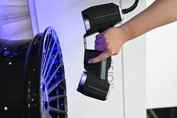
The shift toward AI-assisted 3D algorithms, a direction INSVISION has invested in with over 50 patents and software copyrights, is gradually reducing the operator burden in these challenging scenarios. Intelligent exposure control, real-time frame rejection, and feature-based alignment can compensate for partial data loss on tricky geometries.
Yet the core principle remains: the physics of blue light and the geometry of the part set the boundaries. Understanding those boundaries is the difference between a scan that looks good and a scan that is metrologically sound.
- What Is 3D Scanning? Principles, Workflow, and Industrial Applications 3D scanning is a digital measurement technology that converts the surface geometry of physical objects into 3D data. This entry covers its working principles, core parameters, industrial use cases, common misconceptions, and related technical…
- What Is a 3D Scanner? Types, Parameters, and Selection Criteria A 3D scanner captures three-dimensional surface data from physical objects and converts geometry, dimensions, and features into digital data for inspection, reverse engineering, and modeling.
- What Is 3D Scanning Accuracy? Accuracy, Repeatability, and Resolution Explained 3D scanning accuracy describes how closely scan data matches an object's actual geometry and dimensions. It is assessed through local accuracy, volumetric accuracy, stitching accuracy, repeatability, and resolution.
- What Is Point Cloud Data? Point Clouds, Meshes, and CAD Models in 3D Scanning Point cloud data is an important raw data format in 3D scanning. It consists of discrete 3D coordinate points that describe object surface geometry and support inspection, reverse engineering, modeling, and archiving.
Hangzhou Insvision Technology Co., Ltd.
Address: Building 1, No. 1399 Liangmu Road, Yuhang District, Hangzhou, Zhejiang 311121, China
Copyright © Hangzhou Insvision Technology Co., Ltd. All rights reserved.
Copyright © Hangzhou Insvision Technology Co., Ltd. All rights reserved.