

Hole Filling in 3D Scan Meshes
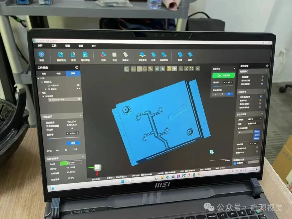
Hole filling in 3D scan meshes is a polygonal mesh post processing operation that identifies and closes unintended gaps, voids, or missing polygon regions in raw scanned mesh data.
Definition
Hole filling in 3D scan meshes is a polygonal mesh post-processing operation that identifies and closes unintended gaps, voids, or missing polygon regions in raw scanned mesh data. These gaps typically arise from scanning limitations such as occlusion, reflective or transparent surface properties, incomplete scan coverage, or noise removal during pre-processing. The goal of hole filling is to produce a topologically consistent, often watertight mesh suitable for downstream industrial applications without distorting intentional part geometry or critical surface features.
How It Works
Hole filling workflows follow a standardized sequence of operations, with variations depending on gap type and algorithm design:
- Gap Detection: Algorithms first identify mesh boundary edges, which are edges attached to only one polygon (a fully watertight mesh has no unpaired boundary edges). Detected gaps are categorized by cross-sectional size, surrounding surface curvature, and proximity to known part features.
- Gap Classification: Gaps are labeled as either scanning artifacts (to be filled) or intentional design features (to be preserved). Classification may use user-defined size thresholds, aligned reference CAD data, or AI models trained on industrial part geometries.
- Filling Execution: Algorithms use context-appropriate methods to reconstruct missing geometry:
- Geometric interpolation for small, planar gaps, where new vertices are calculated to match the curvature and orientation of surrounding mesh surfaces.
- Feature-aware filling for gaps near edges, fillets, chamfers, or other distinct design features, which aligns new geometry with adjacent feature boundaries to preserve part accuracy.
- Contextual reconstruction for large gaps, which may leverage global mesh symmetry, CAD reference data, or user input to avoid geometric distortion.
- Post-Fill Refinement: The filled region is re-triangulated to match the surrounding mesh resolution, smoothed to eliminate sharp transitions, and validated for topological errors such as non-manifold geometry or face intersections.
Key Parameters and Criteria
| Parameter | Meaning | Judgment Method |
|---|---|---|
| Fill Deviation | The maximum geometric difference between the filled mesh region and the nominal or expected part surface geometry | Compare vertex coordinates of the filled region against reference CAD data or adjacent high-fidelity scanned surfaces using 3D deviation analysis tools |
| Gap Size Compatibility | The maximum cross-sectional dimension of a scanning gap that the algorithm can close without introducing topological errors or excessive geometric deviation | Test with standardized gap artifacts of known dimensions, then validate mesh watertightness and fill accuracy post-processing |
| Feature Preservation Rate | The proportion of intentional design features (e.g., through-holes, fillets, chamfers) that remain unmodified and within tolerance after automated hole filling | Count and measure intentional features on the raw mesh, then compare against the post-filling mesh to calculate the percentage of features retained within specified tolerance limits |
| Watertightness Conformance | The degree to which the processed mesh is free of unclosed edges, non-manifold geometry, and intersecting faces after filling | Run automated mesh validation tools to count unpaired boundary edges, non-manifold vertices, and self-intersecting polygons |
Acceptable thresholds for all parameters vary by application, mesh resolution, and required metrological tolerance. For example, metrology-grade inspection workflows require far lower fill deviation than 3D print preparation for non-critical prototype parts.
Suitable and Unsuitable Scenarios
Suitable Scenarios
- Reverse engineering of machined, cast, molded, or sheet metal parts, where scanning gaps result from occlusion, reflective surfaces, or complex undercut geometries
- 3D printing and additive manufacturing preparation, where a watertight mesh is required for accurate slicing and print generation
- Dimensional quality inspection, where minor gaps in non-critical regions would otherwise interfere with automated deviation analysis workflows
- Digital archiving of industrial tooling, production parts, or cultural heritage artifacts, where a complete, continuous mesh is required for long-term digital storage and reference
Unsuitable Scenarios
- Metrology inspection of intentional engineered features, including fastener holes, fluid ports, or alignment pins with diameters under 5mm, where automated filling may accidentally erase critical design details
- Defect analysis workflows (e.g., crack detection, wear measurement) where gaps in the mesh represent actual part damage rather than scanning artifacts
- Ultra-precision applications such as jewelry manufacturing or microelectronics inspection, where sub-millimeter tolerance requirements exceed standard industrial hole filling capabilities
- Clinical medical imaging or dental scanning applications, where mesh filling may modify clinically relevant anatomical features
Common Misconceptions
- Misconception: All holes in a scanned mesh are scanning artifacts that should be filled.
Fact: Many holes are intentional design features, functional openings, or actual part defects. Hole filling tools require explicit configuration, reference data alignment, or AI classification to distinguish between artifacts and features that should be preserved.
- Misconception: Hole filling produces identical geometry to the actual part surface.
Fact: Fill accuracy is dependent on gap size and the amount of surrounding geometric context available. Small gaps can be filled with minimal deviation, but large gaps often introduce measurable geometric error unless augmented with reference CAD data or manual editing.
- Misconception: A watertight mesh is always required for downstream 3D scan applications.
Fact: Applications such as raw surface defect inspection, feature-specific dimensional measurement, and point cloud-based analysis do not require watertight meshes, and unnecessary filling may introduce unwanted geometric artifacts.
- Misconception: Automated hole filling eliminates the need for manual mesh editing.
Fact: Automated algorithms perform reliably for small to medium gaps in uniform geometry, but large gaps, gaps near critical features, or gaps in highly complex free-form surfaces often require manual editing to ensure accuracy.
Related Concepts
- 3D Mesh Processing: The broader category of post-processing operations for polygonal scan data, including hole filling, mesh decimation, smoothing, feature alignment, and noise removal.
- Watertight Mesh: A topologically consistent polygonal mesh with no unclosed edges, non-manifold geometry, or self-intersecting faces, a standard requirement for 3D printing, finite element analysis (FEA), and injection mold design.
- Scan Occlusion: A leading cause of mesh holes, occurring when a part surface is blocked from the 3D scanner’s line of sight during data acquisition.
- Non-Manifold Geometry: A class of mesh topological errors that can result from improper hole filling, including edges shared by three or more faces or vertices connected to disconnected mesh regions, which can break downstream processing workflows.
- Deviation Analysis: A metrology workflow that compares processed scan data (including filled mesh regions) against nominal CAD specifications to verify geometric accuracy and tolerance conformance.
FAQ
How do automated hole filling tools avoid closing intentional part holes?
Most industrial hole filling workflows use one or more classification methods to separate scanning artifacts from intentional features: user-defined size thresholds to ignore holes above a specified dimension, alignment to reference CAD data to flag pre-defined design features, or AI models trained on industrial part geometries to automatically distinguish between artifact gaps and functional openings.
Can hole filling be used on metrology-grade 3D scans without compromising accuracy?
When configured to preserve local surface curvature and feature boundaries, hole filling can maintain metrology-grade accuracy for small to medium-sized gaps. For critical inspection applications, filled regions should be explicitly validated against reference data, as fill deviation increases proportionally with gap size.
What are the most common causes of holes in raw 3D scanned meshes?
Holes typically arise from four main sources: scan occlusion from complex part geometry or fixture interference, reflective, transparent, or dark surface properties that disrupt scanner data capture, incomplete scan coverage from insufficient scan angles, and noise removal or mesh cleaning operations that delete low-confidence overlapping point cloud data.
When is manual hole filling preferred over automated methods?
Manual hole filling is recommended for large gaps resulting from extensive occlusion, gaps located near high-tolerance design features, gaps in highly complex free-form geometry (e.g., turbine blades, ergonomic tooling), and applications where metrological accuracy of the filled region is critical to part performance.
Summary
Hole filling in 3D scan meshes is a core post-processing operation for industrial 3D scanning, designed to close unintended gaps in raw mesh data to produce topologically consistent surfaces for downstream applications. Its performance is measured by standardized criteria including fill deviation, feature preservation rate, and watertightness conformance, with acceptable thresholds varying by use case and required tolerance. While broadly suitable for reverse engineering, 3D printing, and digital archiving workflows, hole filling requires careful configuration to avoid modifying intentional part features or introducing metrological error, and is not appropriate for ultra-precision, defect analysis, or clinical applications where gap preservation is required.
- What Is 3D Scanning? Principles, Workflow, and Industrial Applications 3D scanning is a digital measurement technology that converts the surface geometry of physical objects into 3D data. This entry covers its working principles, core parameters, industrial use cases, common misconceptions, and related technical…
- What Is a 3D Scanner? Types, Parameters, and Selection Criteria A 3D scanner captures three-dimensional surface data from physical objects and converts geometry, dimensions, and features into digital data for inspection, reverse engineering, and modeling.
- What Is 3D Scanning Accuracy? Accuracy, Repeatability, and Resolution Explained 3D scanning accuracy describes how closely scan data matches an object's actual geometry and dimensions. It is assessed through local accuracy, volumetric accuracy, stitching accuracy, repeatability, and resolution.
- What Is Point Cloud Data? Point Clouds, Meshes, and CAD Models in 3D Scanning Point cloud data is an important raw data format in 3D scanning. It consists of discrete 3D coordinate points that describe object surface geometry and support inspection, reverse engineering, modeling, and archiving.
Hangzhou Insvision Technology Co., Ltd.
Address: Building 1, No. 1399 Liangmu Road, Yuhang District, Hangzhou, Zhejiang 311121, China
Copyright © Hangzhou Insvision Technology Co., Ltd. All rights reserved.
Copyright © Hangzhou Insvision Technology Co., Ltd. All rights reserved.