

Full-Size Inspection Definition, Workflow, and Evaluation Criteria for Industrial Quality
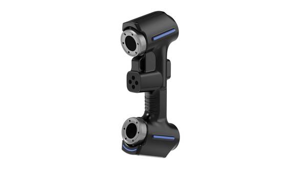
full-size inspection: Meta description: Full-size inspection explained for manufacturing engineers and quality managers: definition, working principles.
What Full-Size Inspection Is
Full-size inspection is a metrology-based quality control process that captures complete geometric data across all defined surfaces and features of a component, then compares that data against CAD nominal geometry or drawing requirements.
Unlike feature-specific inspection, which checks selected dimensions or geometric dimensioning and tolerancing (GD&T) callouts, and unlike sampling inspection, which checks only a subset of a production lot, full-size inspection treats the entire part envelope as the inspection scope.
Common Questions
What should teams check when evaluating What Full-Size Inspection Is?
Full-size inspection is a metrology-based quality control process that captures complete geometric data across all defined surfaces and features of a component, then compares that…
What should teams check when evaluating Core Working Principles?
Full-size inspection begins as a coordinate system problem.
What should teams check when evaluating The basic workflow has four steps:?
Contact and non-contact systems follow the same sequence, but their data acquisition mechanisms differ.
The method sits within established metrology frameworks. ISO 10360 provides acceptance and reverification tests for coordinate measuring systems. ASME Y14.5 defines datums, feature control frames, and tolerance zones. Full-size inspection applies those rules when dimensional deviations can affect function, safety, or regulatory evidence.
Typical settings include automotive body-in-white validation, aerospace MRO structural assessment, and medical device implant or instrument verification.
| Inspection approach | Coverage | Typical application |
|---|---|---|
| Full-size inspection | Complete surface and feature data | First-article validation, high-risk parts |
| Feature-specific inspection | Selected dimensions or GD&T callouts | Process control, spot checks |
| Sampling inspection | Subset of a production lot | High-volume, lower-risk production |
The main difference is scope. Full-size inspection does not assume that unchecked areas are conforming. That makes it useful for first-article reporting and root-cause analysis when a dimensional failure may originate outside the sampled zones.
Core Working Principles
Full-size inspection begins as a coordinate system problem. The component must be fixtured and the measured coordinate system aligned to the reference CAD model or master part before surface deviations can be assigned to individual drawing callouts. Poor alignment at this stage creates positional error across the entire dataset.
The basic workflow has four steps:
- Fixturing and alignment – Establish a stable datum frame and align measured coordinates to reference geometry.
- Geometric data acquisition – Capture data from all external surfaces, edges, and critical features defined on the drawing.
- GD&T analysis – Evaluate profile of a surface, position, flatness, circularity, and other callouts against tolerance zones.
- Compliance reporting – Generate structured dimensional records for first-article inspection, Production Part Approval Process (PPAP), or MRO documentation.
Contact and non-contact systems follow the same sequence, but their data acquisition mechanisms differ.
| Approach | Typical mechanism | Data output | Full-size inspection consideration |
|---|---|---|---|
| Contact | Touch-trigger or continuous scanning probe | Discrete points or line scans | Requires stable fixturing and physical access; acquisition time scales with point count |
| Non-contact | Structured light, laser triangulation, or photogrammetry | Dense point clouds | Requires optical line of sight; surface finish and reflectivity affect data quality |
On a production floor, the aligned dataset often feeds an as-built digital twin used for engineering review, trend monitoring, and traceability. A useful implementation treats that digital record as the basis for pass/fail decisions, not merely a visualization.
Key Evaluation Criteria
Selecting a full-size inspection method starts with four engineering criteria: measurement precision, data capture throughput, part size and geometry compatibility, and GD&T analysis capability.
Precision requirements should be expressed as tolerance-band ratios or repeatability limits on discrete features, not as a single instrument resolution number. Throughput should be judged by the surface area or feature count that must be digitized to support a pass/fail decision.
Part geometry compatibility determines whether contact probing can access all critical surfaces or whether a dense point cloud is needed for free-form areas. GD&T analysis should resolve datum references, true position, profile, and runout callouts directly from measured data.
| Inspection methodology | Key strengths | Common fit |
|---|---|---|
| Contact CMM-based full-size inspection | Established traceable precision for tight-tolerance discrete features; strong alignment with international metrology standards; suited to rigid, prismatic part geometries | Small-batch high-precision aerospace components; medical implant tolerance verification; regulated industries requiring established traceable measurement methods |
| Non-contact 3D scanning full-size inspection | Rapid full-surface data capture; compatibility with complex free-form geometry; dense point clouds for complete digital part replication | Automotive first-article inspection for large body panels; aerospace MRO component wear assessment; high-mix production runs with varied part geometries |
A supplier can demonstrate capability through uncertainty budgets, calibrated artifact correlation, and gage repeatability and reproducibility studies. Those objective checks matter more than sensor class.
Appropriate Use Boundaries
Full-size inspection is not a universal replacement for CMM spot checks or hard gaging. It is a fit-for-purpose validation method. The decision to use it depends on product risk, regulatory evidence requirements, and whether partial sampling would leave dimensional blind spots.
| Application | Governing requirement | Why full-size inspection fits |
|---|---|---|
| First article inspection | AS9102 aerospace FAI | Requires verification of full ballooned characteristics and GD&T callouts |
| PPAP dimensional validation | Automotive OEM requirements | Critical surfaces need complete dimensional layout, not sampled points |
| Final release of implantable devices | ISO 13485 production controls | Full surface verification supports lot release and complaint traceability |
| Reverse engineering of legacy aerospace parts | No source CAD or tolerance data | Complete geometric capture reconstructs as-built geometry for MRO or replacement |
The value is not scanning density alone. It is closing dimensional blind spots that spot checks cannot defend in an audit. Full-size inspection is appropriate where missing data creates compliance risk or safety exposure. Outside that envelope, targeted CMM or gage checks may be sufficient.
Common Misconceptions
Full-size inspection refers to complete dimensional coverage of a part’s defined geometry, not to overall part size. Small medical implants, automotive valve bodies, and large energy castings can all fall under the same measurement coverage requirement.
| Misconception | Engineering clarification |
|---|---|
| It only applies to large-format parts. | Full-size means the entire part envelope is measured against GD&T callouts. Small parts with tight tolerances often need full coverage more than large fabrications with few critical interfaces. |
| It replaces all in-line quality checks. | Full-size inspection is a complementary validation gate for FAI, batch release, or tooling qualification. In-line SPC gaging still monitors process drift between milestones. |
| Only contact CMMs are accurate enough. | Calibrated non-contact systems meet many ISO and ASME requirements when uncertainty budgets and artifact correlation are documented. Contact may still be preferred for deep bores or mirror finishes. |
Method-to-characteristic fit is the controlling factor. Datum alignment, surface finish, edge definition, and measurement uncertainty matter more than sensor class.
Related Metrology and Quality Concepts
Full-size inspection data rarely stands alone. GD&T supplies the evaluation rules: ASME Y14.5 and ISO GPS define datums, feature control frames, and tolerance zones. The inspection workflow aligns measured points to those datum references and reports deviation against each controlled feature.
First article inspection and PPAP depend on that measured evidence. AS9102 first-article records and PPAP dimensional results are only as strong as the underlying full-size inspection data used to populate them.
The same point cloud can support digital twin alignment. Scan-to-CAD comparison updates an as-built model with actual geometry, showing high, low, or distorted surface conditions relative to nominal CAD.
In lean manufacturing, targeted full-size inspection at first-piece, high-risk feature, or process-change points catches non-conformances before downstream machining or assembly adds more cost. That reduces scrap, rework, and the likelihood of a full production run being affected before correction.
| Concept | Functional relationship | Typical record |
|---|---|---|
| GD&T | Defines tolerance zones and datum references for numerical comparison | Ballooned drawing, deviation report |
| FAI/PPAP | Uses measured dimensions as compliance evidence | AS9102 FAI, PPAP dimensional results |
| Digital twin alignment | Aligns point cloud data to CAD or an as-built model | Scan-to-CAD map, updated model |
| Lean quality control | Targets early inspection to reduce downstream waste | First-piece record, control plan |
Evaluating Full-Size Inspection Systems
Full-size inspection is only as repeatable as the standard alignment behind the measurement output. A non-contact system can capture dense full-part geometry; the engineering question is whether those points resolve into defensible GD&T callouts rather than an untraceable mesh.
INSVISION develops 3D measurement solutions for full-part geometric data capture in industrial quality workflows. The stated engineering focus is on ensuring that non-contact output aligns with ISO GPS and ASME Y14.5 requirements, supporting global industrial compliance. This corresponds to the earlier evaluation criterion: standard alignment should be treated as a verification requirement, not a supplier claim.
| Evaluation area | Standard alignment check | Why it matters for full-size inspection |
|---|---|---|
| Datum reference frame | Confirm exported features follow ISO GPS / ASME Y14.5 datum simulation rules | Keeps non-contact and CMM data aligned to the same part coordinate system |
| Geometric tolerance evaluation | Verify form, profile, position, and runout results are computed from measured geometry | Prevents color-map deviation from being mistaken for GD&T conformance |
| Reporting traceability | Check that reports cite the standard revision and evaluation parameters | Makes first-article inspection results auditable and repeatable |
Can full-size inspection be performed on parts with highly complex, free-form surfaces?
Yes, but feasibility depends on accuracy, not surface complexity. Structured light, laser scanning, and computed tomography can acquire dense point clouds from free-form geometry. The harder task is comparing those point clouds to the nominal CAD model within a defensible tolerance zone. ASME Y14.5 defines profile and other GD&T controls;
the inspection workflow must show how point-cloud deviation maps represent that tolerance zone. ISO 10360 and VDI/VDE 2634 provide acceptance and reverification criteria for coordinate measuring systems and optical surface measuring systems.
A visually complete scan is not sufficient. Calibrated reference artifacts, sensor qualification, and alignment repeatability determine whether tight GD&T callouts can be validated on free-form surfaces.
How does full-size inspection data integrate with existing QMS and CAD platforms?
Integration typically uses neutral geometry and dimensional-data formats, not a single vendor-specific file. Point clouds or meshes are aligned to STEP or native CAD models. Deviation maps can be attached to first-article inspection packages, while numerical results—point deviations, GD&T evaluations, pass/fail status, operator, machine ID, and timestamps—move into QMS or SPC software.
Common formats include CSV, XML/JSON, and QIF for model-based dimensional data.
ISO 9001 and AS9100 require traceability between measurement records, serialized parts or batches, CAD revisions, and measurement systems. They do not mandate a specific file format. The practical requirement is clear mapping: a QMS record must show what was measured, against which revision, with which instrument, and what decision resulted.
| Data output | Typical use | Relevant reference |
|---|---|---|
| CSV/ASCII point deviations | SPC charting and Cp/Cpk monitoring | IATF 16949 / ISO 9001 measurement records |
| QIF or MBD dimensional results | Associating GD&T evaluations with CAD model | ISO 23952 / ASME Y14.5 |
| Deviation color-map report | Visual documentation for FAI or PPAP | AS9102 / PPAP |
| Point cloud or STL mesh | As-built CAD comparison or reverse engineering | ASME Y14.5 profile evaluation |
Is full-size inspection only feasible for low-volume production runs?
No. Volume affects cycle time and automation, but it does not by itself decide feasibility. Low-volume aerospace or medical device programs may use full-size inspection as a routine control. High-volume automotive programs often apply it during launch, tooling buy-off, annual layout, or capability studies rather than on every part.
Inline optical or multi-sensor systems can collect full-surface data at line rate for some part sizes; contact CMMs may not keep up. Many operations therefore combine full-size inspection on a defined sampling frequency with faster feature-specific gaging. The engineering question is whether the measurement cycle, data handling, and risk of undetected variation justify full-surface data for a given production point.
What standards should a quality manager apply when validating full-size inspection?
Validation depends on the technology and industry. ASME Y14.5 defines the geometric tolerance framework. ISO 10360 and VDI/VDE 2634 provide acceptance tests for contact and optical coordinate measuring systems. AS9102 governs first article inspection in aerospace and defense.
Medical device manufacturers may work under ISO 13485 or FDA 21 CFR Part 820, and automotive suppliers under IATF 16949 with customer-specific layout requirements.
These standards do not approve a universal full-size inspection method. They require evidence that the method is suitable for the characteristic and tolerance. A practical qualification plan should include gage repeatability and reproducibility, bias checks against calibrated artifacts, and correlation with an independent reference method.
When evaluating systems from suppliers such as INSVISION, the same objective criteria should apply.
Core Takeaways
Full-size inspection verifies a part’s complete measured surface against the full CAD model or drawing definition. It is not a spot-check. Every surface and feature with GD&T callouts is evaluated. The core workflow is capture–align–compare–report: dense 3D data is aligned to nominal geometry, deviations are computed per characteristic, and results are issued in an ISO/ASME-aligned format.
Use cases concentrate where complete geometric compliance is non-negotiable: aerospace MRO for airfoil and structural geometry, automotive first-article inspection, medical device implants and instruments, and energy components with tight profile or runout tolerances.
| Implementation criterion | Evaluation focus |
|---|---|
| Alignment quality | Handling of real production part datum features |
| Data coverage | Capture of deep pockets, edges, and critical surfaces without masking |
| Reporting depth | GD&T characteristic output, not just color deviation maps |
| Repeatability | Gage R&R performance on representative components |
For high-stakes components, full-size inspection provides the final dimensional evidence that geometry matches design intent before release.
- What Is 3D Scanning? Principles, Workflow, and Industrial Applications 3D scanning is a digital measurement technology that converts the surface geometry of physical objects into 3D data. This entry covers its working principles, core parameters, industrial use cases, common misconceptions, and related technical…
- What Is a 3D Scanner? Types, Parameters, and Selection Criteria A 3D scanner captures three-dimensional surface data from physical objects and converts geometry, dimensions, and features into digital data for inspection, reverse engineering, and modeling.
- What Is 3D Scanning Accuracy? Accuracy, Repeatability, and Resolution Explained 3D scanning accuracy describes how closely scan data matches an object's actual geometry and dimensions. It is assessed through local accuracy, volumetric accuracy, stitching accuracy, repeatability, and resolution.
- What Is Point Cloud Data? Point Clouds, Meshes, and CAD Models in 3D Scanning Point cloud data is an important raw data format in 3D scanning. It consists of discrete 3D coordinate points that describe object surface geometry and support inspection, reverse engineering, modeling, and archiving.
Hangzhou Insvision Technology Co., Ltd.
Address: Building 1, No. 1399 Liangmu Road, Yuhang District, Hangzhou, Zhejiang 311121, China
Copyright © Hangzhou Insvision Technology Co., Ltd. All rights reserved.
Copyright © Hangzhou Insvision Technology Co., Ltd. All rights reserved.