

Datum Alignment in 3D Scanning
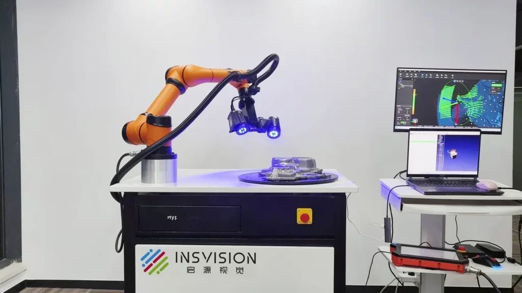
Datum alignment in 3D scanning is the metrological process of transforming captured 3D point cloud or mesh data to align with a predefined, traceable datum reference frame (DRF) that conforms to engineering design, manufacturing, or inspection requirements.
Definition
Datum alignment in 3D scanning is the metrological process of transforming captured 3D point cloud or mesh data to align with a predefined, traceable datum reference frame (DRF) that conforms to engineering design, manufacturing, or inspection requirements. Unlike general scan registration, which aligns multiple scan passes to each other to form a unified model, datum alignment establishes a consistent, standardized coordinate system for comparing scan data to nominal design specifications, integrating with other digital engineering datasets, or supporting repeatable measurement workflows.
How It Works
Datum alignment follows a structured, metrologically traceable workflow:
- DRF Definition: The target datum reference frame is established prior to scanning, typically derived from a CAD model’s specified datum features, physical reference artifacts, or facility-wide coordinate systems for large-volume applications.
- Feature Capture: The 3D scanning system captures either inherent part datum features (e.g., machined planes, precision bores, mounting edges) or dedicated fiducial markers attached to the part or workspace, which correspond to reference points in the DRF.
- Registration Calculation: Scanning software uses a registration algorithm to compute the rigid body transformation (translation and rotation) required to align the captured scan features to their nominal positions in the DRF. Common alignment schemes include the 3-2-1 method, which constrains 3 degrees of freedom with a primary planar datum, 2 with a secondary linear datum, and 1 with a tertiary point datum, as well as best-fit and fiducial-based registration for non-standard geometries.
- Validation: The alignment result is validated by measuring deviation between captured reference features and their nominal DRF positions to confirm accuracy meets workflow requirements. For large-volume or mobile scanning workflows, optical tracking systems may maintain continuous alignment across multiple scan passes without re-registration of individual datasets.
Key Parameters and Criteria
All parameter performance varies based on scanner type, part material and surface finish, datum feature size and accessibility, environment lighting, and software calibration status.
| Parameter | Meaning | Judgment Method |
|---|---|---|
| Alignment Accuracy | The magnitude of deviation between the position of datum features in the aligned scan dataset and their nominal positions in the target datum reference frame | Calculate root mean square (RMS) error across corresponding datum feature points, or compare critical dimensional measurements from the aligned scan to values from a calibrated reference metrology artifact |
| Datum Feature Repeatability | The variation in alignment results when the same alignment workflow is executed repeatedly on the same part under identical operating conditions | Perform 10 or more consecutive alignment runs, then compute the standard deviation of measured alignment error values across all runs |
| DoF Constraint Completeness | The degree to which all 6 rigid body degrees of freedom (X, Y, Z translation; RX, RY, RZ rotation) are fixed relative to the datum reference frame | Attempt manual translation and rotation of the aligned scan dataset within scanning software to confirm no unconstrained movement is possible |
| Alignment Robustness to Noise | The ability of the alignment algorithm to produce consistent, accurate results when scan data contains surface noise, partial feature capture, or minor surface artifacts | Introduce controlled levels of scan noise (via software simulation or real-world surface conditioning), then measure the change in alignment error relative to a low-noise baseline |
Suitable and Unsuitable Scenarios
Suitable Scenarios
- Dimensional quality inspection of machined, cast, molded, or additive manufactured parts against nominal CAD specifications
- Assembly validation where multiple component scans must be aligned to a common assembly-level datum reference frame
- Reverse engineering of legacy parts where design datums must be replicated to ensure replacement parts fit into existing assemblies
- Large-volume scanning of structures such as aerospace fuselages, heavy equipment, or ship components, where multiple scan stations or mobile scans require a unified facility-wide reference frame
- Automated inline scanning workflows in high-volume manufacturing, where consistent, repeatable alignment is required for 100% inspection of production parts
Unsuitable Scenarios
- Scanning of unfeatured, homogeneous objects with no identifiable inherent datum features or space for fiducial marker attachment
- Non-industrial applications with no formal engineering reference frame, such as consumer-grade photogrammetry for casual 3D modeling
- Alignment of non-rigid, deformable parts without supporting dynamic tracking or non-rigid registration infrastructure
- Ultra-precision applications with tolerance requirements below the alignment accuracy threshold of standard industrial 3D scanning systems, including microelectronics manufacturing, fine jewelry production, and dental restoration scanning
- Scanning of objects with datum features too small to be reliably resolved by the scanning system, such as holes with diameters below 5mm or surface details smaller than 2mm
- Non-medical, non-industrial human or facial scanning for consumer use cases, where no formal metrological reference frame is required
Common Misconceptions
- Misconception: All alignment methods produce equivalent results. Fiducial-based, feature-based, and best-fit alignment methods have differing accuracy, repeatability, and use case suitability, depending on part geometry, datum feature accessibility, and workflow requirements. For example, best-fit alignment may minimize overall surface deviation but does not adhere to formal engineering datum schemes required for GD&T inspection.
- Misconception: Higher scan resolution automatically improves alignment accuracy. Alignment accuracy depends primarily on the quality of datum feature capture, algorithm robustness, and system calibration, rather than overall scan resolution. Sufficient sampling of datum features to resolve their geometry is required, but additional resolution beyond this threshold does not typically improve alignment performance.
- Misconception: Datum alignment is only necessary for dimensional inspection workflows. While a core use case for inspection, datum alignment is also critical for reverse engineering (to ensure replacement parts match original design datums), assembly validation (to align multiple component scans to a common assembly reference frame), and digital twin creation (to integrate scan data with enterprise engineering datasets).
- Misconception: The 3-2-1 alignment method works for all part geometries. The 3-2-1 method requires accessible, well-defined planar, linear, and point datum features. Complex free-form parts (e.g., aerospace turbine blades, automotive body panels) with no distinct planar datums may require alternative schemes such as fiducial-based alignment or feature-based alignment using curved or irregular datum features.
Related Concepts
- 3D Scan Registration: The broader process of aligning multiple partial scan datasets to each other to form a single unified 3D model; datum alignment is a specialized subset of registration focused on alignment to an external predefined reference frame.
- Datum Reference Frame (DRF): A standardized, mutually perpendicular coordinate system defined by a set of reference planes, axes, and points, used as the basis for all dimensional measurements and design specifications for a part or assembly.
- Geometric Dimensioning and Tolerancing (GD&T): A symbolic language for defining and communicating engineering tolerances, which typically specifies the datum features and reference frame required for part inspection alignment.
- Fiducial Marker: A high-contrast, dimensionally stable physical marker with a known center coordinate, used to provide consistent reference points for alignment in scenarios where inherent part features are insufficient.
- Optical Tracking: A metrological technology that uses calibrated cameras to track the 3D position and orientation of scanners, parts, or markers in real time, enabling continuous alignment during large-volume or mobile scanning workflows.
- Best-Fit Alignment: An alignment method that calculates a transformation to minimize the overall root mean square (RMS) deviation between a scan dataset and a reference model, used when no formal predefined datum features are available.
FAQ
What is the difference between datum alignment and general scan registration?
General scan registration aligns multiple partial scan datasets to each other to create a single cohesive 3D model, with no requirement for alignment to an external predefined coordinate system. Datum alignment is a specialized form of registration that aligns scan data specifically to a formal, predefined datum reference frame (typically derived from CAD or engineering specifications) to support dimensional inspection, assembly validation, or other engineering workflows that require a consistent, traceable reference basis.
When should I use feature-based alignment vs. fiducial-based alignment?
Feature-based alignment is preferred when parts have clearly defined, accessible inherent datum features (e.g., machined planes, bores, mounting holes) that match the engineering DRF, as it eliminates the need for attaching markers and reduces preparation time. Fiducial-based alignment is more suitable for parts with few or no distinct inherent features, free-form geometries, or scenarios where higher alignment repeatability is required, as long as marker placement does not interfere with part function or scan coverage.
Can datum alignment be performed on flexible or deformable parts?
Standard rigid datum alignment assumes the scanned part is a rigid body with no deformation during scanning. For flexible parts, alignment requires additional infrastructure such as dynamic tracking systems to measure part deformation during scanning, or specialized non-rigid alignment algorithms that account for measured geometric changes.
How do I verify the accuracy of a datum alignment?
Alignment accuracy is typically verified by measuring the deviation of known reference features on the part (e.g., calibrated gauge blocks, traceable artifact features) from their nominal coordinates in the DRF. Common metrics include root mean square (RMS) error of datum feature points, and comparison of critical dimensional measurements on the aligned scan to calibrated measurement values from a reference metrology tool.
Summary
Datum alignment is a foundational metrological process in industrial 3D scanning that enables consistent, traceable comparison of scan data to engineering design specifications. By aligning captured 3D datasets to a predefined datum reference frame, it supports core use cases including dimensional inspection, reverse engineering, assembly validation, and digital twin integration. Performance varies based on alignment method selection, datum feature quality, and scanning system calibration, making it critical to match alignment workflows to specific application requirements and accuracy needs.
- What Is 3D Scanning? Principles, Workflow, and Industrial Applications 3D scanning is a digital measurement technology that converts the surface geometry of physical objects into 3D data. This entry covers its working principles, core parameters, industrial use cases, common misconceptions, and related technical…
- What Is a 3D Scanner? Types, Parameters, and Selection Criteria A 3D scanner captures three-dimensional surface data from physical objects and converts geometry, dimensions, and features into digital data for inspection, reverse engineering, and modeling.
- What Is 3D Scanning Accuracy? Accuracy, Repeatability, and Resolution Explained 3D scanning accuracy describes how closely scan data matches an object's actual geometry and dimensions. It is assessed through local accuracy, volumetric accuracy, stitching accuracy, repeatability, and resolution.
- What Is Point Cloud Data? Point Clouds, Meshes, and CAD Models in 3D Scanning Point cloud data is an important raw data format in 3D scanning. It consists of discrete 3D coordinate points that describe object surface geometry and support inspection, reverse engineering, modeling, and archiving.
Hangzhou Insvision Technology Co., Ltd.
Address: Building 1, No. 1399 Liangmu Road, Yuhang District, Hangzhou, Zhejiang 311121, China
Copyright © Hangzhou Insvision Technology Co., Ltd. All rights reserved.
Copyright © Hangzhou Insvision Technology Co., Ltd. All rights reserved.