

Core Principles, Key Parameters, and Applications of Automated 3D Scanning
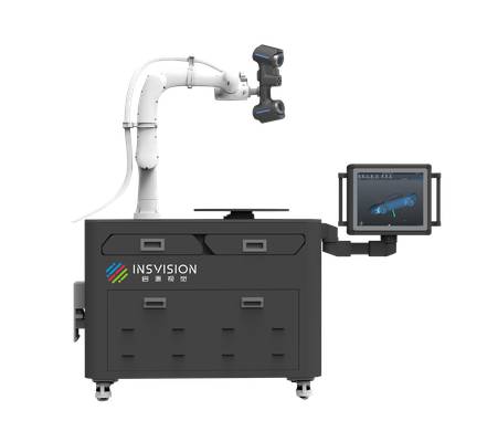
automated 3D scanning: What Is Automated 3D Scanning? Automated 3D scanning is a non-contact industrial metrology technology that captures full-field.
What Is Automated 3D Scanning?
Automated 3D scanning is a non-contact industrial metrology technology that captures full-field dimensional data without continuous manual operator input. A pre-programmed scan path drives the sensor across the measured surface. The resulting point cloud or mesh then feeds automated reporting workflows for GD&T callouts, pass/fail decisions, or first-article inspection.
Scenario Snapshot
A practical way to read the article is through this scenario:
- What Is Automated 3D Scanning?: Automated 3D scanning is a non-contact industrial metrology technology that captures full-field dimensional data w…
- Core Working Principles of Automated 3D Scanning Sy…: Automated 3D scanning is a controlled measurement loop, not a sensor pointed at a part.
- Key Performance Parameters for Automated 3D Scannin…: Automated 3D scanning systems are not interchangeable.
Manual 3D scanning depends on an engineer guiding the scanner for every setup and often completing alignment and report export by hand. Automated systems reduce that variability through repeatable sensor motion and scripted data processing.
| Factor | Manual 3D scanning | Automated 3D scanning |
|---|---|---|
| Scan path | Operator-guided per cycle | Pre-programmed and repeatable |
| Reporting | Manual alignment and export | Automated deviation maps or pass/fail output |
| ISO 10360 role | Operator-level verification | System-level geometric validation remains required |
In regulated manufacturing, ISO 10360 geometric inspection standards provide the framework for verifying scanner accuracy and geometric error. Automated scanning does not remove this validation. It makes an accepted measurement process more repeatable and auditable.
Core Working Principles of Automated 3D Scanning Systems
Automated 3D scanning is a controlled measurement loop, not a sensor pointed at a part. The part is presented repeatably, scanned without contact, registered to nominal geometry, and output as an inspection record. A typical workflow moves through six stages.
| Stage | Typical function |
|---|---|
| Part fixturing | A fixture or pallet locates datum features and clamps the part without covering surfaces that require scan coverage. |
| Motion and positioning | A rotary stage, gantry, or robot arm indexes the part or scanner through preset orientations. |
| Data capture | Structured light or laser projection records surface points without touching the part. |
| Point cloud to mesh | Raw point data is filtered, merged, and meshed into an inspection-ready surface. |
| CAD alignment | The scan mesh is aligned to nominal CAD using datum features or best-fit routines. |
| Report output | GD&T callouts, deviation color maps, and pass/fail flags are exported. |
Motion integration turns individual scans into a repeatable cycle. Robotic arms, gantries, or rotary stages execute stored scan paths, reducing operator influence and keeping measurement data consistent for first-article inspection, production sampling, or aerospace MRO checks.
In Industry 4.0 smart factory frameworks, these systems commonly exchange data through PLC handshakes, file drops, or MES/QMS connections. Dimensional results then move into traceability records rather than remaining in isolated inspection files.
Key Performance Parameters for Automated 3D Scanning Solutions
Automated 3D scanning systems are not interchangeable. Evaluation should first tie metrology capability to dimensional tolerance requirements, then address throughput and integration. The table below lists parameters engineering and quality teams use during solution selection.
| Parameter | Definition | Industrial relevance |
|---|---|---|
| Measurement accuracy | Degree of agreement between scanned dimensional values and a traceable reference part, validated per ISO 10360 where applicable | Critical in aerospace and medical device manufacturing where dimensional compliance is mandatory |
| Scan volume | Maximum physical space a system can capture in a single scan cycle or full motion path | Determines compatibility with part sizes from small medical components to large aerospace structures |
| Cycle time | Total time required to complete scanning, data processing, and inspection reporting | Affects throughput for high-volume production lines and lean manufacturing targets |
| Point cloud density | Number of data points captured per unit of surface area | Influences detection of small surface defects and fine geometric features |
| Integration capability | Ability to connect with MES, QMS, CAD platforms, conveyors, and robotic cells | Supports data flow for Industry 4.0 and digital twin workflows |
A common misconception is that higher point cloud density always improves inspection quality. It can increase file size and processing time without adding dimensional information. Cycle time should also be judged against tolerance and feature requirements, not in isolation. First-article inspection on a complex casting with tight GD&T callouts may justify a longer cycle than a fast check on a stamped bracket.
Valid Use Boundaries for Automated 3D Scanning
A valid use boundary defines the operating envelope where automated 3D scanning produces repeatable dimensional data under known conditions. It is not a list of exclusions. It marks the deployment contexts where scan coverage, registration stability, and measurement uncertainty align with required tolerance.
Validated contexts cluster around several industrial conditions: stable part presentation, controlled ambient light and vibration, repeatable scan paths, and surfaces that can be scanned without excessive preparation.
| Application context | Proven operating conditions | Typical metrology deliverable |
|---|---|---|
| High-volume production line inline inspection | Fixed or robot-mounted scanner, stable fixturing, known cadence | CAD comparison, GD&T callouts, high-frequency dimensional checks |
| Repeat part batch quality checks | Similar geometry, repeatable fixture setup, known surface finish | First-article and batch dimensional reports |
| Regulated industry compliance audits | Traceable calibration, documented routines, controlled environmental limits | Audit-ready records linked to ASME/ISO inspection criteria |
| Digital twin data capture | Aerospace MRO, automotive OEM, medical device, and renewable energy components with scan-friendly surfaces | As-built point clouds, wear mapping, and dimensional deviation models |
Boundaries should be read as validation limits, not weaknesses. When a part falls outside these conditions—such as a highly specular surface or unstable fixturing—the appropriate engineering response is to adjust surface preparation, fixturing, or scan configuration before relying on automated dimensional output.
Common Misconceptions About Automated 3D Scanning
Several recurring assumptions lead engineers to dismiss automated 3D scanning before checking how a system handles actual inspection requirements.
| Misconception | Correction |
|---|---|
| Works only on matte, light-colored parts. | Structured-light and laser scanners handle machined metals, castings, dark composites, and reflective surfaces through controlled exposure and blue-light or laser illumination. |
| Requires advanced programming or vision expertise. | Many systems run predefined inspection routines. Operators load a part, select a program, and review pass/fail output. Quality engineers typically build the program once. |
| Does not align with ASME Y14.5 GD&T workflows. | Reporting modules can output profile, position, runout, and other GD&T callouts directly against CAD nominal geometry. |
| Legacy factory integration is too difficult. | Systems exchange data through STEP, IGES, CSV, QIF, or DXF and communicate with MES/SCADA through digital I/O, TCP/IP, or PLC handshakes. |
These points do not describe every scanner on the market, but they reflect common capabilities in modern automated 3D scanning systems.
Related Industrial Metrology Concepts
Automated 3D scanning does not replace coordinate measuring machines (CMMs); it provides a different measurement channel. A CMM delivers traceable contact measurements with low uncertainty on discrete GD&T callouts, such as position, profile, and runout.
Automated 3D scanning captures dense point clouds across complex freeform surfaces, making it useful for first-article inspection, as-built capture, and rapid comparison to CAD. Two-dimensional vision inspection still handles high-speed presence/absence, edge, and surface defect checks where 3D form is not required. Hand tools remain the first line for bore diameter, snap gages, and quick floor checks.
Within lean manufacturing, automated 3D scanning reduces non-value-added waiting and rework by converting a physical part into digital data earlier and more frequently. The scan data can be aligned to ASME Y14.5 datum reference frames and evaluated against profile or position tolerances.
In digital twin workflows, the same point cloud becomes the as-built geometry for PLM updates, maintenance records, and design revision feedback.
| Method | Primary role | Typical production use |
|---|---|---|
| CMM | Traceable contact measurement of critical GD&T features | Final inspection, capability studies |
| 2D vision | Fast non-contact presence, edge, and defect checks | In-process sorting, surface defect detection |
| Hand tools | Low-cost direct dimensional checks | Floor checks, setup verification |
| Automated 3D scanning | Dense non-contact surface capture and CAD comparison | First-article inspection, complex geometry, digital twin |
Automated 3D Scanning Solutions From INSVISION
In production metrology, automated 3D scanning is sensor-based dimensional capture triggered without manual probe repositioning. The distinction from manual scanning is not raw speed but control: fixed standoff, defined motion path, stable lighting or laser geometry, and automatic alignment to CAD or datum features. Repeatability depends on these factors more than on point density.
Before selecting a system, engineers should separate data acquisition from measurement capability.
| Evaluation area | Key question |
|---|---|
| Repeatability | Does the system produce stable deviations on a traceable artefact? |
| Metrology alignment | Are results reported against ISO 10360, ASME B89, or a stated internal standard? |
| Factory integration | Can triggers, PLC handshakes, and MES/QMS reports be configured without custom middleware? |
| GD&T output | Does software evaluate profile, position, and runout tolerances directly from scan data? |
INSVISION develops industrial metrology systems in this category. The AlphaAutoScan-400 automated 3D inspection system is one purpose-built example for repeatable inline and offline inspection tasks. It is engineered to align with international metrology standards and supports integration with existing factory execution systems for Industry 4.0 workflows. Evaluation should still follow the criteria above.
Frequently Asked Questions About Automated 3D Scanning
What regulatory standards apply to automated 3D scanning for aerospace and medical manufacturing?
Aerospace work typically falls under AS9100/AS9103 and ASME Y14.5 GD&T. The scanner itself is not a certified standard; measurement outputs must be validated through gage R&R or ISO 10360-style checks. Medical device data are governed by ISO 13485 and FDA 21 CFR Part 11 for electronic records.
Can automated 3D scanning systems work with existing CAD and quality management software?
Yes. Common export formats include STEP, IGES, QIF, and CSV. CAD platforms consume point clouds and meshes for nominal-to-actual comparison. QMS integration usually occurs at the reporting layer, feeding flagged dimensions and SPC data into nonconformance or PPAP software.
What types of parts are well-suited for automated 3D scanning inspection?
| Part characteristic | Suitability |
|---|---|
| Freeform surfaces, complex castings, composites | High |
| Thin-wall sheet metal and molded parts | High |
| Deep internal bores or narrow slots | Low unless combined with probing |
| Mirror-polished surfaces | Medium; spray or polarization may be needed |
How does automated 3D scanning fit first-article inspection?
It reduces reliance on limited touch-probe sampling by capturing full surface geometry. AS9102 FAI still requires ballooned drawing characteristics; scanning supplies measurement evidence for profile, flushness, and visible position checks.
Key Takeaways for Industrial Metrology Teams
Automated 3D scanning refers to a measurement workflow in which a structured light or laser sensor moves along a programmed or robot-guided path, triggers acquisition automatically, and builds a dense point cloud of the part. Instead of relying on an operator to position a probe at individual points, the system follows repeatable scan trajectories.
Software then aligns the captured data to the CAD model and evaluates surface deviations against defined GD&T callouts or tolerance bands.
For metrology teams, evaluation should focus on parameters that determine whether the data is usable for acceptance decisions:
| Parameter | What it affects |
|---|---|
| Volumetric accuracy | Maximum deviation across the working volume |
| Repeatability | Consistency across multiple scan cycles |
| Point spacing and resolution | Ability to resolve small features and edge breaks |
| Scan speed and cycle time | Throughput for inline or near-line inspection |
| Environmental stability | Performance under vibration, temperature shifts, and shop lighting |
| Inspection software | CAD alignment, GD&T extraction, reporting, and traceability |
Validated use cases include first-article inspection and PPAP dimensional layouts in automotive tier supply, airfoil and blade profile checks in aerospace MRO, and high-mix medical device component verification. In each case, the value is not faster scanning alone but controlled, repeatable data collection that supports ISO/ASME-compliant documentation and reduces operator-to-operator variation.
- What Is 3D Scanning? Principles, Workflow, and Industrial Applications 3D scanning is a digital measurement technology that converts the surface geometry of physical objects into 3D data. This entry covers its working principles, core parameters, industrial use cases, common misconceptions, and related technical…
- What Is a 3D Scanner? Types, Parameters, and Selection Criteria A 3D scanner captures three-dimensional surface data from physical objects and converts geometry, dimensions, and features into digital data for inspection, reverse engineering, and modeling.
- What Is 3D Scanning Accuracy? Accuracy, Repeatability, and Resolution Explained 3D scanning accuracy describes how closely scan data matches an object's actual geometry and dimensions. It is assessed through local accuracy, volumetric accuracy, stitching accuracy, repeatability, and resolution.
- What Is Point Cloud Data? Point Clouds, Meshes, and CAD Models in 3D Scanning Point cloud data is an important raw data format in 3D scanning. It consists of discrete 3D coordinate points that describe object surface geometry and support inspection, reverse engineering, modeling, and archiving.
Hangzhou Insvision Technology Co., Ltd.
Address: Building 1, No. 1399 Liangmu Road, Yuhang District, Hangzhou, Zhejiang 311121, China
Copyright © Hangzhou Insvision Technology Co., Ltd. All rights reserved.
Copyright © Hangzhou Insvision Technology Co., Ltd. All rights reserved.