

Understanding AI 3D Scanning Core Principles Key Parameters and Industrial Use Boundaries
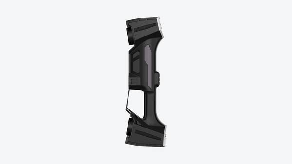
ai 3d scanning: Definition and Core Function of AI 3D Scanning Definition and Core Function of AI 3D Scanning AI 3D scanning is a non-contact industrial.
Definition and Core Function of AI 3D Scanning
AI 3D scanning is a non-contact industrial measurement technology. It combines 3D data capture hardware—typically structured light or laser triangulation—with artificial intelligence algorithms that process, interpret, and optimize the resulting point cloud or mesh data. The AI component does not replace the physical scanner.
It automates what happens after photons hit the sensor: noise filtering, feature recognition, hole identification, alignment, and even dimensional extraction against CAD models.
Term Notes
AI 3D scanning is a non-contact industrial measurement technology.
Working Principles of Industrial AI 3D Scanning SystemsIndustrial AI 3D scanning combines structured light projection, high-density point cloud capture, and machine-learning-based…
Why Blue Laser Technology MattersBlue laser light operates at a shorter wavelength than red laser alternatives — roughly 450nm versus 650nm.
Key Performance Parameters for Industrial AI 3D ScanningEvaluating an AI 3D scanning system for industrial use requires moving past datasheet headline numbers and examining the par…
Traditional 3D scanning produces raw geometric data that often requires hours of manual cleanup and surface reconstruction. AI 3D scanning shifts that burden to trained models that recognize industrial features—edges, bores, cut boundaries—and process them consistently across repeated scans. This matters in production environments where measurement repeatability and operator independence are as important as raw accuracy.
The distinction from conventional scanning is not one of hardware capability but of software autonomy:
| Aspect | Traditional 3D Scanning | AI 3D Scanning |
|---|---|---|
| Data cleanup | Manual, operator-dependent | Automated noise classification and removal |
| Feature recognition | User-selected regions | Algorithmic detection of holes, edges, surfaces |
| Scan path planning | Experience-driven, trial-and-error | Adaptive exposure and line selection |
| Repeatability | Varies with operator skill | Standardized processing reduces variance |
| Integration with inspection | Export then analyze | Direct CAD comparison and GD&T extraction |
In the context of Industry 4.0, AI 3D scanning functions as a data acquisition layer that feeds digital twins, closed-loop quality systems, and lean manufacturing cells. Automotive OEMs use it for first-article inspection and in-line dimensional verification of stamped or cast components. Aerospace MRO operations rely on it for wear analysis and reverse engineering of legacy parts where original CAD data is unavailable.
Medical device manufacturers apply it to implant surface characterization and surgical instrument validation, where cleanroom compatibility and sub-millimeter repeatability are non-negotiable. Energy sector applications span turbine blade profiling, pipe wall thickness mapping, and flange face inspection.
The core function is not simply capturing geometry faster. It is reducing the human decision points between data acquisition and actionable measurement results. AI handles the interpretive layer—deciding which points are signal and which are noise, which features matter and which are artifacts.
This reduces manual processing time, improves measurement consistency across operators and shifts, and supports the lean objective of eliminating non-value-added inspection labor.
Working Principles of Industrial AI 3D Scanning Systems
Industrial AI 3D scanning combines structured light projection, high-density point cloud capture, and machine-learning-based processing to convert physical parts into measurable digital data. The workflow moves in three stages: capture, preprocessing, and analysis.
- Data Capture via Laser Projection
The scanner projects a pattern of blue laser lines onto the part surface. Cameras mounted at fixed angles record how each line deforms across the geometry. Triangulation converts these deformations into XYZ coordinates, producing a point cloud that can exceed millions of points per scan. Multiple laser line configurations serve different purposes. Single-line modes reach into deep holes and recesses.
Multi-line modes — 7, 17, 26, or 50 parallel lines depending on the system — cover broader surfaces faster. Scanning areas typically range from 650mm × 550mm for benchtop systems to 2200mm × 2200mm for large-format equipment.
- AI-Powered Preprocessing
Raw point clouds contain noise, outliers, and misaligned frames. AI algorithms handle these problems before any dimensional analysis begins.
| Preprocessing Task | Function | Industrial Benefit |
|---|---|---|
| Noise filtering | Removes stray points caused by ambient light or edge reflections | Cleaner data for downstream measurement |
| Multi-frame alignment | Registers overlapping scans into a single coordinate system | Eliminates manual stitching errors |
| Feature recognition | Identifies holes, cut edges, and critical part features automatically | Reduces operator-dependent variability |
Intelligent hole identification is particularly relevant for parts with drilled or machined openings. Instead of relying on an operator to rescan missed areas, the system flags incomplete hole data and triggers targeted recapture.
- AI-Driven Analysis
Once the point cloud is clean and registered, the analysis stage extracts actionable outputs.
- Geometric dimensioning: The system measures distances, diameters, angles, and GD&T callouts directly from the point cloud. Deviations from nominal CAD data appear as color-mapped reports.
- Surface anomaly detection: Machine-learning models flag dents, scratches, porosity, or weld defects that deviate from the expected surface profile.
- CAD-compatible model generation: For reverse engineering or legacy part documentation, the system converts the point cloud into a mesh or parametric CAD model.
Why Blue Laser Technology Matters
Blue laser light operates at a shorter wavelength than red laser alternatives — roughly 450nm versus 650nm. This physical property matters on the shop floor. Shiny, reflective, or machined metal surfaces scatter red laser light unpredictably, producing noisy data.
Blue laser projection reduces this scatter, allowing reliable capture on polished stainless steel, aluminum castings, and complex freeform geometries without spray coating or surface preparation. The result is faster setup and fewer failed scans on parts that would challenge older structured-light systems.
The end-to-end workflow — capture, clean, analyze — replaces manual measurement methods that require hard gauges, CMM programming, or subjective visual inspection. For quality managers and manufacturing engineers, the practical value lies in repeatability: the same scan produces the same measurement regardless of operator skill or shift.
Key Performance Parameters for Industrial AI 3D Scanning
Evaluating an AI 3D scanning system for industrial use requires moving past datasheet headline numbers and examining the parameters that dictate day-to-day performance on real parts. A scanner that excels in a laboratory demo may struggle on a production floor with mixed surface finishes, tight GD&T callouts, or awkward geometry. Four categories matter most when matching a system to an application.
First, consider the physical capture envelope. The scanning area defines the maximum surface a unit can digitize in a single pass. This figure determines whether the tool suits small orthopedic implants, mid-sized automotive brackets, or large energy-sector housings. A larger area reduces the number of scans needed for big parts, but it may come at the cost of resolution on fine features.
Conversely, a compact scan area offers higher detail but slows throughput on large assemblies.
Second, assess scanning mode flexibility. Industrial parts rarely present uniform geometry. A casting may include deep recesses, while a stamped panel demands high-speed surface capture. Systems that offer distinct modes—such as a precision setting with multiple laser lines and a deep-hole mode using a single line—let operators adapt to the part instead of forcing the part to adapt to the scanner.
This flexibility directly affects first-article inspection cycle times and the ability to capture hard-to-reach features without excessive repositioning.
Third, examine AI feature recognition capability. Modern systems embed algorithms that automatically identify holes, cut edges, and surface transitions within the point cloud. This functionality reduces the manual segmentation work that historically consumed hours of metrology engineer time.
It also supports consistent alignment to CAD models and helps standardize inspection results across different operators—a key concern when ISO or ASME documentation requirements apply.
Fourth, understand the laser configuration. Blue laser diodes have become the default for industrial scanning because they perform reliably on reflective or dark surfaces that scatter red laser light. The number of laser lines matters too: fewer lines generally yield higher precision on complex geometry, while higher line counts accelerate data capture on larger, smoother surfaces.
| Parameter Category | Technical Description | Industrial Application Relevance |
|---|---|---|
| Scanning Area | Maximum surface area a scanner can capture in a single pass | Determines compatibility with part sizes, from small medical components to large energy sector assemblies; impacts batch scanning throughput |
| Scanning Mode Flexibility | Availability of specialized capture modes (e.g., precision, high-speed, deep hole) for different part geometries | Allows users to optimize scanning for tight tolerance requirements, high-volume production, or hard-to-reach features |
| AI Feature Recognition Capability | Built-in algorithms that automatically identify part features such as holes, cut edges, and surface characteristics | Reduces manual point cloud editing time, streamlines GD&T alignment, and supports consistent inspection results across operators |
| Laser Configuration | Number and type of laser lines used for data capture | Blue laser configurations deliver reliable performance on reflective surfaces; varying line counts balance speed and precision for different use cases |
These parameters should be assessed against the specific tolerance stack-ups and material conditions present in your facility. A system that handles one combination well may not transfer cleanly to another without validation.
Industrial Use Boundaries of AI 3D Scanning
Industrial Use Boundaries of AI 3D Scanning
AI 3D scanning is not a universal replacement for every measurement tool on the shop floor. Its value concentrates where three conditions overlap: non-contact acquisition is required, surface geometry is complex enough to defeat conventional CMM probing, and the downstream workflow benefits from dense point-cloud data rather than discrete point readings. Outside those conditions, simpler tools often remain more practical.
The strongest fit is precision dimensional verification on parts with freeform surfaces, deep pockets, or thin edges. A machined automotive powertrain housing with tight GD&T callouts benefits because AI-assisted scanning captures thousands of surface points in a single pass, then aligns them to CAD for deviation mapping.
The same logic applies to aerospace MRO damage assessment, where a worn turbine blade or impact-damaged leading edge must be characterized quickly and compared against repair limits. Medical implant verification works well because orthopedic components combine organic curvature with strict dimensional tolerances — a combination that frustrates touch probing but suits structured-light scanning.
Operational context matters as much as part geometry.
| Operational Context | Typical Workflow Fit | Value Driver |
|---|---|---|
| In-line production inspection | Automated or semi-automated cell near the line | Rapid pass/fail feedback without removing parts to a lab |
| Quality lab metrology | First-article inspection, capability studies, root-cause analysis | Dense data supports GD&T evaluation and trend tracking |
| Digital twin data capture | Reverse engineering, as-built documentation, MRO records | Full-surface mesh output feeds simulation and archival systems |
Standards alignment is a practical boundary condition, not an afterthought. For AI 3D scanning to serve as valid inspection evidence in Western manufacturing, the measurement workflow must support traceable verification against ISO 10360-series acceptance tests for coordinate measuring systems and ASME Y14.5 GD&T evaluation methods.
This means the scanner output must be exportable to metrology software that performs feature extraction and tolerance evaluation using recognized algorithms — not proprietary black-box scoring.
A misconception worth correcting: AI in this context does not mean the scanner independently decides whether a part passes. The AI layer typically improves mesh reconstruction, noise filtering, and feature recognition. The acceptance decision still belongs to the metrology software, the engineer, and the documented tolerance framework.
INSVISION systems, for example, provide the acquisition hardware and software foundation for these workflows, but the compliance boundary is defined by how the data is evaluated downstream.
Common Misconceptions About AI 3D Scanning
Common Misconceptions About AI 3D Scanning
Misconceptions about AI 3D scanning tend to spread faster than the technology itself. In industrial settings, these inaccuracies can distort purchasing decisions and lead teams to deploy systems that don’t match their actual inspection requirements. Three myths come up repeatedly in conversations with quality engineers and metrology managers.
Myth 1: AI 3D scanning eliminates the need for skilled operators. The reality is more nuanced. AI does reduce manual intervention for repetitive tasks — auto-segmenting scan data, filtering noise, and aligning point clouds without constant user input. But trained operators remain essential for complex part geometries, fixture setup, and validating results against GD&T callouts.
An AI system cannot decide whether a surface profile deviation matters for a sealing face versus a cosmetic surface. That judgment requires someone who understands the part’s function and the applicable ISO or ASME standard. Think of AI as removing the tedium, not the expertise.
Myth 2: All AI 3D scanners deliver identical performance. This assumption collapses quickly when you examine parameter configurations. Scan area, laser line counts, and hole-rescanning behavior differ materially across systems. For instance, some configurations support scanning areas up to 650mm × 550mm, while large-area systems reach 2200mm × 2200mm.
Deep-hole scanning may rely on a single blue laser line, while high-speed modes use 26 or 50 parallel lines. These aren’t trivial differences — they determine whether a scanner can capture a turbine blade root or a stamped bracket without excessive repositioning.
| Evaluation Parameter | Typical Range / Configuration | Relevance to Application Fit |
|---|---|---|
| Scanning area | Up to 650mm × 550mm; large-area systems up to 2200mm × 2200mm | Determines part size coverage per scan pass |
| Deep-hole scanning | 1 single blue laser line | Critical for bores, pockets, and recessed features |
| High-speed scanning | 26–50 parallel blue laser lines | Balances throughput vs. data density |
| Precision scanning | 7–17 parallel blue laser lines | Higher point density for tight tolerance zones |
| Hole rescanning | Intelligent identification of holes and cut edges | Reduces missed data on drilled or punched features |
Myth 3: AI 3D scanning only works for small, high-precision parts. This likely stems from early adoption in dental and electronics applications. Industrial AI scanning now spans a much broader envelope. The same underlying approach — structured light with AI-assisted data processing — handles tiny medical components and large welded assemblies. What changes is the optical configuration, not the fundamental capability.
A system configured for a 650mm × 550mm scan area suits automotive brackets and housings. A large-area system covering 2200mm × 2200mm per scan pass addresses aerospace panels and energy-sector fabrications. Application fit matters more than part size alone.
The practical takeaway: evaluate AI 3D scanning systems against your specific inspection criteria — scan area, feature complexity, tolerance requirements, and operator workflow — rather than relying on generalized assumptions about what the technology can or cannot do.
Related Concepts in Industrial Metrology
Related Concepts in Industrial Metrology
Industrial professionals encounter AI 3D scanning within a broader framework of measurement science. Understanding adjacent terms clarifies how the technology fits existing quality workflows.
Non-contact inspection acquires surface geometry without physical touch, eliminating part deflection and enabling measurement of soft or complex components. AI 3D scanning falls squarely in this category, using structured light or laser projection rather than tactile probes.
Point cloud processing converts raw scan data into usable geometry. Millions of XYZ coordinates require filtering, alignment, and mesh generation before analysis. AI accelerates this by automating noise removal and feature recognition that previously demanded manual intervention.
Geometric dimensioning and tolerancing (GD&T) provides a standardized language for defining allowable variation per ASME Y14.5 or ISO 1101. AI-assisted scanning simplifies extraction of GD&T callouts—flatness, position, profile—directly from dense scan data, reducing interpretation errors during first-article inspection.
Digital thread and digital twin integration rely on continuous data flow between physical assets and virtual models. AI 3D scanning feeds as-built conditions into digital twins, enabling comparison against nominal CAD and supporting closed-loop corrective action.
Industry 4.0 metrology embeds measurement within automated production cells rather than isolated lab environments. AI-driven scanning supports inline inspection at production speed, providing statistical process control data without bottlenecking throughput.
| Concept | Role of AI 3D Scanning | Relevant Standard |
|---|---|---|
| Non-contact inspection | Acquires geometry without part deformation | ISO 10360 |
| Point cloud processing | Automates filtering and feature extraction | — |
| GD&T extraction | Simplifies callout measurement from scan data | ASME Y14.5, ISO 1101 |
| Digital twin integration | Supplies as-built geometry to virtual models | ISO 23247 |
| Industry 4.0 metrology | Enables inline measurement at production rates | ISO 9001, IATF 16949 |
Industrial AI 3D Scanning Solution Context
Industrial AI 3D Scanning Solution Context
AI 3D scanning in industrial settings is not a single technology but a combination of measurement hardware, laser projection modes, and software algorithms that interpret point-cloud data. The term “AI” here refers primarily to feature recognition, hole identification, and automated data segmentation rather than generative or conversational capabilities.
An engineer evaluating these systems should separate hardware performance from software intelligence; a scanner may capture excellent geometry yet offer limited automated interpretation, or vice versa.
Application fit starts with the physical envelope. A scanner sized for small machined components will be unsuitable for large castings or airframe sections, while a large-area system may lack the resolution required for fine medical device features. Scanning mode selection follows a similar logic. Single-line blue laser modes suit deep holes, pockets, and occluded edges.
Multi-line modes accelerate surface capture but can introduce noise in narrow recesses. The evaluation question is whether the system can switch modes without changing the inspection workflow.
AI feature sets should be assessed against the specific inspection tasks the facility performs. Intelligent identification of holes and cut edges, for example, supports automated rescanning of critical features that are often missed in first-pass capture.
This matters in automotive body-in-white inspection, where hole position and edge condition are frequent GD&T callouts, and in aerospace MRO, where fastener hole wear must be tracked over service intervals.
The table below outlines application-focused criteria for matching AI 3D scanning capabilities to industrial inspection requirements.
| Evaluation Criterion | Key Question | Industrial Relevance |
|---|---|---|
| Scanning area capacity | Does the field of view match the largest part in the production mix? | Prevents stitching errors on large components; small-area scanners on large parts increase measurement uncertainty |
| Scanning mode range | Are single-line and multi-line blue laser modes available? | Single-line handles deep holes and edges; multi-line speeds up broad surface capture |
| AI feature recognition | Can the software identify holes, cut edges, or other features automatically? | Enables targeted rescanning of critical features without manual intervention |
| Workflow integration | Does AI output align with existing inspection sequences? | Reduces rework in first-article inspection and production QC loops |
| Sector-specific requirements | Can the system accommodate surface finishes and geometries typical of the application? | Aerospace MRO, medical device, and energy components impose different reflectivity and access constraints |
INSVISION develops AI-integrated 3D scanning systems for industrial use cases in automotive, aerospace, medical device, and energy sectors.
Its scanning solutions offer varied scanning area capacities—from approximately 650 mm × 550 mm up to 2200 mm × 2200 mm depending on configuration—along with multiple blue laser scanning modes, including single-line deep hole scanning, 7-line precision scanning, and higher-density multi-line modes for high-speed surface capture.
AI-driven feature recognition supports quality control, production optimization, and maintenance workflows. The relevant evaluation is whether these capabilities align with the part geometry, inspection priorities, and data handling requirements of a given facility.
What types of industrial materials are compatible with AI 3D scanning?
AI 3D scanning works across most materials found in manufacturing environments, but performance varies by surface condition. Machined metals, castings, injection-molded plastics, composites, and ceramics generally scan well. The main limitation is optical: dark, glossy, or transparent surfaces can scatter or absorb laser light, reducing point cloud density.
Standard practice for difficult surfaces includes applying a temporary matting spray or developer powder. Reflective finishes such as polished stainless steel or chrome plating typically require surface preparation. Porous or fibrous materials like certain foams and untreated carbon fiber can also produce noisy data.
AI-assisted scanning algorithms help by intelligently filtering stray reflections and reconstructing geometry from partial data, but they do not eliminate the underlying optical constraints. For first-article inspection on shiny components, factor surface preparation into workflow planning.
How do AI 3D scanning results align with ISO and ASME measurement standards?
AI 3D scanning systems produce dense point clouds that can be compared against CAD nominals using GD&T callouts, but the scanner itself is a data acquisition tool — it does not independently certify compliance with ISO 10360 or ASME Y14.5.
What matters is the metrology workflow: scanner accuracy must be verified against calibrated artifacts traceable to national standards, and the software used for dimensional analysis must support the relevant tolerance frameworks. Many facilities use AI 3D scanning for rapid first-article inspection and then validate critical dimensions with CMM spot checks.
The scan data can support ASME Y14.5 feature control frames, profile tolerances, and surface comparison reports, provided the measurement uncertainty is documented. AI algorithms that auto-align scans and detect geometric features can speed up reporting, but the underlying measurement uncertainty budget remains the responsibility of the quality engineer.
Can AI 3D scanning integrate with existing manufacturing software systems?
Most industrial AI 3D scanning platforms export standard file formats — STL, PLY, OBJ, and increasingly STEP or native CAD formats — that downstream systems can consume.
| Integration Target | Typical Use | Data Format |
|---|---|---|
| CAD/CAM software | Reverse engineering, design updates | STEP, IGES, native CAD |
| Inspection software | GD&T reporting, color maps | STL, PLY, point cloud |
| PLM/PDM systems | Document control, revision management | Neutral CAD, PDF reports |
| SPC/quality dashboards | Trend analysis, process capability | CSV, XML, API calls |
AI-based feature recognition can automatically extract hole positions, slot dimensions, and surface profiles, reducing manual post-processing. However, seamless integration depends on the software ecosystem: some systems offer direct plugins for major CAD and inspection packages, while others require intermediate file conversion.
Procurement teams should verify compatibility with existing licenses before committing to a specific scanning platform.
What environmental conditions support optimal AI 3D scanning performance?
AI 3D scanning is more tolerant of shop-floor conditions than traditional CMM measurement, but environmental factors still affect data quality. Temperature stability matters most: thermal expansion of the part and scanner can introduce dimensional errors, particularly on large components.
Most manufacturers specify an operating temperature range, typically 5°C to 40°C, with calibration performed at the expected working temperature. Vibration from nearby machinery can blur laser lines and degrade accuracy, so isolated or damped mounting is recommended. Ambient lighting is less critical for blue laser systems than for older white-light scanners, but direct sunlight can still interfere.
Dust, oil mist, and coolant spray should be controlled around the scanning area. For high-precision work, allow the scanner and part to thermally stabilize before measurement, and avoid scanning near HVAC vents or open bay doors.
Core Takeaways for AI 3D Scanning in Industry
Core Takeaways for AI 3D Scanning in Industry
Industrial performance hinges on three measurable parameters. Scanning area defines the maximum field of view per capture pass. Mode flexibility refers to the number and configuration of laser lines available for different surface conditions. AI feature recognition governs how reliably the software identifies geometric features without operator intervention.
| Parameter | Practical Meaning in Inspection |
|---|---|
| Scanning area | Maximum part footprint captured in a single pass; larger areas reduce setup repositioning |
| Scanning mode flexibility | Single-line modes for deep holes; multi-line modes for faster surface coverage |
| AI feature recognition | Automated identification of holes, cut edges, and surface transitions |
The technology applies across automotive stamping checks, aerospace MRO inspections, medical device validation, and energy-sector component audits. It also supports compliance with ISO and ASME metrology frameworks when used with traceable calibration artifacts.
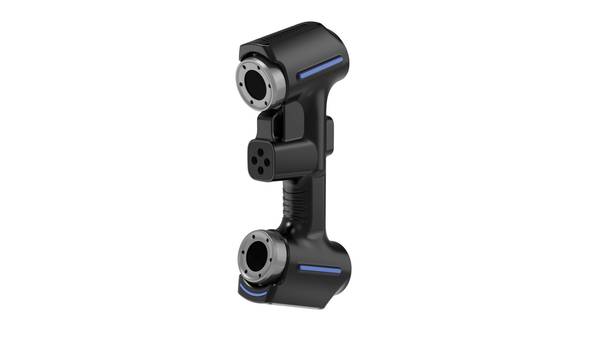
AI 3D scanning is now a standard tool within modern industrial metrology and digital transformation initiatives. Its value lies in reducing inspection bottlenecks while maintaining repeatable, standards-aligned measurement records.
- What Is 3D Scanning? Principles, Workflow, and Industrial Applications 3D scanning is a digital measurement technology that converts the surface geometry of physical objects into 3D data. This entry covers its working principles, core parameters, industrial use cases, common misconceptions, and related technical…
- What Is a 3D Scanner? Types, Parameters, and Selection Criteria A 3D scanner captures three-dimensional surface data from physical objects and converts geometry, dimensions, and features into digital data for inspection, reverse engineering, and modeling.
- What Is 3D Scanning Accuracy? Accuracy, Repeatability, and Resolution Explained 3D scanning accuracy describes how closely scan data matches an object's actual geometry and dimensions. It is assessed through local accuracy, volumetric accuracy, stitching accuracy, repeatability, and resolution.
- What Is Point Cloud Data? Point Clouds, Meshes, and CAD Models in 3D Scanning Point cloud data is an important raw data format in 3D scanning. It consists of discrete 3D coordinate points that describe object surface geometry and support inspection, reverse engineering, modeling, and archiving.
Hangzhou Insvision Technology Co., Ltd.
Address: Building 1, No. 1399 Liangmu Road, Yuhang District, Hangzhou, Zhejiang 311121, China
Copyright © Hangzhou Insvision Technology Co., Ltd. All rights reserved.
Copyright © Hangzhou Insvision Technology Co., Ltd. All rights reserved.