

Understanding 3D Scanning Workflow Definition, Principles, Parameters, and Boundaries
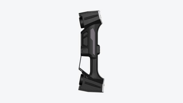
Understanding 3D Scanning Workflow Definition, Principles, Parameters, and Boundaries. 3d scanning workflow: What Is a 3D Scanning Workflow?
What Is a 3D Scanning Workflow?
What Is a 3D Scanning Workflow?
A 3D scanning workflow is a standardized, sequential process for capturing the geometric surface data of a physical object and converting that data into an accurate digital 3D model. In industrial practice, the workflow is not merely the act of scanning; it encompasses planning, data acquisition, alignment, post-processing, and export of a mesh or point cloud for downstream engineering use.
The core functional purposes of a structured 3D scanning workflow fall into four primary categories within Western manufacturing environments:
| Purpose | Typical Application |
|---|---|
| Quality inspection | Comparing scanned geometry against nominal CAD data to produce color-mapped deviation reports |
| Reverse engineering | Reconstructing CAD models from legacy parts, tooling, or hand-modified components where no drawings exist |
| Digital twin data ingestion | Feeding as-built geometry into simulation, layout, or asset management systems |
| Part validation | Verifying first-article inspection requirements, GD&T callouts, and form tolerances |
Within Industry 4.0 frameworks, the 3D scanning workflow functions as a bridge between physical assets and digital records. Unlike traditional contact measurement using coordinate measuring machines (CMMs), which captures discrete points along predefined paths, a scanning workflow captures dense surface data across the entire visible geometry.
This distinction matters for lean manufacturing initiatives: CMM inspection often becomes a bottleneck when feature counts rise, whereas a scanning workflow can acquire full-field data in a single acquisition sequence. That said, CMMs retain advantages for certain tight-tolerance features, particularly deep bores or surfaces requiring tactile verification. The two methods are complementary, not mutually exclusive.
A traceable quality management system benefits from the repeatability of a defined scanning workflow. Documented parameters — scan resolution, alignment strategy, reference geometry, and export tolerances — allow inspection results to be audited and reproduced. This traceability aligns with ISO 9001 and AS9100 expectations, where measurement processes must be controlled and verifiable.
Suppliers such as INSVISION provide scanning hardware that fits within these controlled workflows, though the workflow itself remains a process definition independent of any single instrument.
Core Working Principles of a Standard Industrial 3D Scanning Workflow
An industrial 3D scanning workflow converts physical geometry into usable digital data through a controlled sequence. Unlike ad-hoc digitizing, formal workflows prioritize repeatability and metrological traceability, aligning with ISO 10360 acceptance tests and ASME Y14.5 GD&T definitions.
Scenario Snapshot
A practical way to read the article is through this scenario:
- Core Working Principles of a Standard Industrial 3D…: An industrial 3D scanning workflow converts physical geometry into usable digital data through a controlled sequen…
- Key Evaluation Criteria for Industrial 3D Scanning…: Industrial adoption of 3D scanning is rarely a simple purchase decision.
- Use Boundaries of 3D Scanning Workflows: A 3D scanning workflow fits best when the measurement task matches the technology’s physical and optical character…
Pre-scan preparation establishes the datum environment. Fixturing must constrain the part without inducing distortion, while reference markers or targets are placed to enable scanner self-location during multi-angle capture. For reflective or transparent surfaces, a temporary matte coating is applied to ensure laser reflectivity remains within sensor tolerance.
These preparation parameters are documented as part of the measurement setup record.
Data capture follows, using laser projection and sensor acquisition to record surface points. Processing then filters noise, aligns individual scans, and meshes the point cloud into a polygonal model. Validation compares this model against nominal CAD geometry, extracting GD&T deviations such as profile, position, and runout callouts.
Final outputs include inspection reports, reverse-engineered CAD models, and digital thread feeds for downstream PLM or MES systems. Each phase—setup parameters, scan settings, alignment residuals, and validation results—is logged to support audit trails required in aerospace, medical device, and energy sectors.
| Workflow Phase | Key Activity | Typical Documentation |
|---|---|---|
| Pre-scan preparation | Fixturing, marker placement, surface treatment | Setup photos, target coordinates |
| Data capture | Laser projection, sensor acquisition | Scanner settings, operator ID |
| Point cloud processing | Noise filtering, alignment, meshing | Alignment RMS error, mesh resolution |
| Model validation | CAD comparison, GD&T evaluation | Deviation color maps, tolerance reports |
| Final output | Report generation, data export | Signed inspection reports, QIF/STEP files |
Key Evaluation Criteria for Industrial 3D Scanning Workflows
Industrial adoption of 3D scanning is rarely a simple purchase decision. Engineering and quality teams evaluate a proposed 3D scanning workflow against a set of technical and operational criteria that determine whether the system can produce repeatable, auditable data within the constraints of a production environment.
The correct alignment depends on part geometry, material surface properties, required measurement uncertainty, and how downstream data will be used.
Common evaluation criteria center on four areas: coverage, capture flexibility, measurement traceability, and integration with existing data systems. These are not abstract preferences. In aerospace and medical device manufacturing, traceability to national metrology standards is often a non-negotiable requirement for AS9100 or FDA 21 CFR Part 11 record-keeping.
In automotive body shops, data processing integration with CAD and digital twin platforms determines whether scan data can move into root-cause workflows without manual rework.
The table below organizes the primary criteria and the industrial application contexts where each carries the most weight.
| Evaluation Criterion | Technical Definition | Common Industrial Application Fit |
|---|---|---|
| Scanning area coverage | The maximum physical surface area a scanning system can capture in a single pass, measured in millimeters | Best suited for large-format aerospace component inspection and automotive body panel alignment |
| Scanning mode flexibility | The availability of specialized capture settings for different part features (e.g., deep holes, fine surface details) | Best suited for medical device implant inspection and energy turbine components with complex internal geometries |
| Measurement traceability | The ability to link scan data to national metrology standards for audit compliance | Best suited for aerospace AS9100 quality programs and medical device FDA 21 CFR Part 11 record-keeping |
| Data processing integration | Compatibility with existing CAD, QMS, and digital twin software platforms | Best suited for high-volume automotive production lines and Industry 4.0 digital thread initiatives |
For procurement stakeholders, these criteria translate into a practical checklist. A system that covers 650mm×550mm in a single pass may serve most aerospace subassemblies well, but a large-format turbine casing demands much larger coverage.
Similarly, a workflow that includes both multi-line precision scanning and a single blue laser line for deep hole capture allows one system to address both surface geometry and internal features without switching hardware. The evaluation exercise is about matching documented capabilities to the specific use case, not about generic feature counts.
Use Boundaries of 3D Scanning Workflows
Use Boundaries of 3D Scanning Workflows
A 3D scanning workflow fits best when the measurement task matches the technology’s physical and optical characteristics. The practical boundary is not a hard size limit but a resolution-to-area tradeoff. Free-form surfaces, deep pockets, and medium to large parts generally suit blue laser scanning well. Very small features with tight GD&T callouts may require cross-checking against tactile CMM data.
| Fit Category | Best-Fit Scenario | Caution Zone |
|---|---|---|
| Part geometry | Free-form surfaces, complex internal features | Micron-level features below scanner resolution |
| Part size | Medium to large parts | Parts requiring coordinate accuracy beyond optical limits |
| Production volume | Low-volume custom parts, first-article inspection | High-volume 100% inline check without automation |
| Compliance | Aerospace, medical, automotive, energy | Unvalidated processes for audit-ready reporting |
Alignment with established quality standards matters more than scanner specifications. Regulated teams should validate the 3D scanning workflow against ISO or ASME requirements before deployment. INSVISION systems support this when scanning areas up to 650mm×550mm, using single-line deep hole scanning or multi-line precision modes as the application demands.
Common Misconceptions About Industrial 3D Scanning Workflows
A persistent myth in Western manufacturing is that a 3D scanning workflow requires no pre-scan preparation. Engineers sometimes assume the scanner simply “captures everything.” In practice, achieving ISO-compliant accuracy on large or featureless surfaces demands deliberate setup. Reference marker placement, surface matting, and controlled ambient lighting directly affect point cloud density and dimensional traceability.
Skipping these steps leads to noisy data that fails first-article inspection criteria.
Another misconception holds that all 3D scanning workflows deliver identical precision. Accuracy is not a single fixed value. It varies with laser line configuration, scan distance, and object geometry. A wide-area scan may prioritize speed, while a deep-hole scan requires a different optical mode. Quality managers should link accuracy claims to specific GD&T callouts rather than a generic “high precision” label.
Procurement teams also assume 3D scanning cannot integrate with legacy quality systems. Modern workflows export neutral mesh and CAD formats that feed directly into existing QMS software, supporting lean continuous improvement without replacing established inspection protocols. Finally, 3D scanning is not limited to reverse engineering.
Validating MRO parts, building digital twins, and conducting in-process geometric verification are equally common industrial applications.
Related Concepts in Industrial 3D Metrology
Related Concepts in Industrial 3D Metrology
A 3D scanning workflow does not operate in isolation. In production environments, it functions as the data acquisition layer for a series of adjacent metrology and digital manufacturing processes. Understanding these relationships matters for engineers evaluating where scanning fits into an existing quality ecosystem.
Core Adjacent Concepts
| Concept | Definition | Relationship to 3D Scanning Workflow |
|---|---|---|
| Point Cloud Processing | Conversion of raw scan data into meshes, surfaces, or CAD-comparable geometry | Downstream step; determines whether scan data becomes usable engineering output |
| GD&T Alignment | Registration of scanned point clouds to nominal CAD using geometric datum features | Enables dimensional inspection against ASME Y14.5 or ISO GPS callouts |
| Digital Thread | Continuous data linkage from design through manufacturing, inspection, and service | Scanning provides the as-built geometry record that populates the thread |
| CMM Hybridization | Combining tactile CMM data with optical scan data in one inspection report | Expands coverage: CMM for tight tolerances, scanning for full-surface characterization |
| Reverse Engineering | Reconstruction of CAD models from physical parts lacking digital definitions | Direct application of scan-to-CAD workflows, common in legacy tooling and MRO |
| Predictive Maintenance Digital Twins | As-operated digital models updated with measured geometry and wear data | Periodic scanning feeds dimensional drift analysis into asset management systems |
Why the Foundations Matter
Point cloud processing is the immediate technical dependency. Raw scan data contains noise, overlapping passes, and variable density. The processing pipeline—filtering, alignment, mesh generation—dictates downstream usability. A scan workflow that captures clean, structured data reduces processing time and preserves edge definition for features like holes, slots, and cut edges.
GD&T alignment deserves particular attention in Western manufacturing contexts. Aerospace and automotive suppliers routinely work to ASME Y14.5 or ISO 1101 standards. A scanning workflow must support datum-based alignment rather than simple best-fit registration when inspection reports need to match CMM outputs. Best-fit alignment can mask form errors by distributing deviation across the entire surface.
Datum-constrained alignment isolates deviation where the drawing says it matters.
CMM hybridization reflects practical reality in most quality departments. Tactile CMMs remain the reference standard for dimensional certification, particularly for true position and profile tolerances in the micron range. Optical scanning adds value where CMMs struggle: freeform surfaces, dense point acquisition, and rapid first-article verification.
The two methods increasingly coexist within unified inspection software, with scan data providing context around CMM-verified features.
The digital thread concept ties scanning to broader Industry 4.0 initiatives. As-built geometry captured during production becomes the record against which later deviations are measured. For traceability, this matters in regulated sectors—medical device manufacturing and aerospace both require documented evidence that produced parts match design intent.
A structured 3D scanning workflow generates that evidence without adding inspection bottlenecks.
Predictive maintenance digital twins represent a newer application. By periodically scanning high-wear components—turbine blades, injection molds, stamping dies—maintenance teams can track dimensional change over time. This shifts maintenance from scheduled intervals to condition-based triggers.
Practical Boundaries
Not every scanning concept applies to every application. Reverse engineering requires different processing strategies than inspection. A part being reverse-engineered has no CAD reference; the workflow must generate one from scan data alone. Inspection assumes a nominal model exists and measures deviation from it. Confusing these two modes produces poor results in both directions.
Similarly, scan resolution requirements differ by application. A digital twin for predictive maintenance may tolerate lower point density than a first-article inspection report. Defining the end use before configuring the scanning workflow prevents over- or under-scanning.
INSVISION systems address several of these workflow stages through configurable scanning modes—including precision line sets for surface characterization and single-line modes for deep-hole access—but the broader point here is conceptual: scanning is the data capture layer, not the entire metrology process.
Role of Specialized 3D Scanning Solutions in Workflow Optimization
A 3D scanning workflow is not a single action but a sequence of capture, processing, and analysis steps. The efficiency of that sequence depends heavily on whether the scanning hardware can adapt to different geometric features without forcing a change in methodology.
Many industrial parts present mixed challenges: a broad, smooth surface that must be captured quickly, alongside a deep bore or a tight edge radius that requires a narrower, more controlled laser line. If the scanner cannot switch modes, the operator either compromises on coverage or moves to a secondary tool, which breaks measurement traceability and slows the overall inspection cycle.
Specialized solutions address this by consolidating capture modes within a single system. For example, a scanner may offer a single blue laser line for deep hole scanning, a set of parallel blue laser lines for precision surface measurement, and a higher line count—such as 26 or 50 blue laser lines—for high-speed full-part scanning. Switching between these modes is a workflow decision, not a hardware swap.
The measurement data remains within one software environment and one calibration chain.
INSVISION represents one example of this specialized approach. Its industrial scanners use blue laser technology and support multiple scanning modes to handle deep hole feature capture, precision surface measurement, and high-speed scanning across areas up to 650 mm × 550 mm, depending on the configuration.
The underlying purpose is not to add features for their own sake, but to keep the 3D scanning workflow continuous: capture, verify, and document without transferring parts between instruments or re-establishing alignment datums.
| Scanning Mode | Typical Geometry | Workflow Role |
|---|---|---|
| Single blue laser line | Deep holes, narrow slots, cut edges | Captures recessed features that parallel-line modes miss |
| 7–17 parallel blue laser lines | Precision surfaces, GD&T callouts | High-resolution area measurement for tight tolerances |
| 26–50 parallel blue laser lines | Large, smooth surfaces | Rapid full-part digitization for first-article or incoming inspection |
The table above reflects how mode selection maps to feature type rather than to a specific brand. In a Western manufacturing context—automotive OEM, aerospace MRO, or medical device production—this mapping matters because ISO and ASME standards require traceable measurement data regardless of which geometric feature is being checked.
A scanner that forces the operator to change tools between a deep bore and a flat datum surface introduces an additional source of variation. A system that keeps those modes under one metrology framework reduces that risk.
From a quality manager’s perspective, the practical benefit is auditability. When a single scanning platform produces the data for a deep hole, a precision surface, and a high-speed full-part scan, the resulting inspection report references one instrument, one calibration record, and one software export path.
That is often more defensible in a supplier audit than a report assembled from multiple devices with different uncertainty budgets.
Misconceptions persist around high line counts. More laser lines do not automatically mean better measurement quality. Higher line counts accelerate capture on open surfaces, but they can also introduce noise or lose small features in shadowed areas. A well-designed 3D scanning workflow uses the high-speed mode where speed is appropriate and switches to a single-line or precision mode where geometry demands it.
The optimization lies in knowing which mode the part requires at each stage, not in defaulting to the fastest setting.
This is where specialized technology earns its place. INSVISION’s blue laser scanners, as one example, are built around that mode-switching principle. Blue laser light offers practical advantages on reflective or dark industrial surfaces, but the more important contribution to workflow optimization is the ability to move between capture modes without losing alignment or exporting data to a separate software package.
That continuity is what turns 3D scanning from a series of disconnected measurements into a repeatable, documented process.
For industrial buyers evaluating such systems, the criteria should not be a marketing comparison of line counts or scanning areas in isolation. Evaluation should focus on whether the system supports the full range of geometries present in the current production mix, whether mode transitions are fast enough for the required takt time, and whether the measurement output can be traced to a single calibration record.
A 3D scanning workflow that fails any of those three tests will likely create more documentation burden than it removes, regardless of the hardware’s published specifications.
Frequently Asked Questions About 3D Scanning Workflows
What international quality standards apply to industrial 3D scanning workflow outputs?
Most Western manufacturers anchor acceptance criteria to ISO 10360 (CMM verification) and ASME B89.4.22 for volumetric performance. While 3D scanners are not CMMs, verification workflows often reference VDI/VDE 2634 Part 2 for optical surface-based systems. For GD&T callouts, outputs should be traceable to a calibrated artifact within the same thermal envelope as production parts.
Aerospace MRO and medical device buyers typically require AS9102 first-article inspection reports or ISO 13485 documentation, not raw scan data.
How do 3D scanning workflows integrate with existing CAD and quality management systems?
Most modern workflows export neutral formats—STEP, IGES, or QIF—directly into PLM or QMS software. The practical barrier is rarely file format; it is the density of the mesh. Downstream CAD packages often require decimation or NURBS surfacing before meaningful comparison. A clean workflow validates the scan-to-CAD deviation color map against GD&T callouts before any report is signed.
What pre-scan steps ensure ISO 10360-compliant measurement results?
Thermal stabilization, reference artifact verification, and surface preparation matter more than scanner specs. Matte developer spray is common on reflective or dark surfaces. The scanner should be warmed up, and the artifact measured at the same ambient temperature as the part. Without these steps, repeatability claims are meaningless.
Can 3D scanning workflows support high-volume production inspection environments?
Yes, when integrated with automated fixturing and pass/fail thresholds. High-volume lines favor structured-light systems with fast capture rates and automated cell logic. Specialized solutions such as those from INSVISION address workflow optimization where blue laser line configurations support both precision and speed modes.
The constraint is usually data handling, not scan time—point cloud processing must keep pace with takt time or the bottleneck shifts to the workstation.
Summary of 3D Scanning Workflow Core Concepts
Summary of 3D Scanning Workflow Core Concepts
A 3D scanning workflow is the structured sequence of activities that converts physical geometry into a usable digital dataset for inspection, reverse engineering, or digital manufacturing purposes. At its core, the workflow answers three questions: what needs to be captured, how the capture should be executed, and what constitutes an acceptable result.
The formal definition centers on repeatability. A workflow is not simply running a scanner over a part — it is a documented process with defined inputs, parameters, and acceptance criteria. Without that structure, scan data quality varies from operator to operator and shift to shift.
Core sequential steps typically include preparation, scanning, data processing, and evaluation. Preparation covers surface treatment, reference target placement, and scanner configuration. Scanning involves selecting the appropriate mode — precision, high-speed, or deep-hole capture depending on geometry. Processing aligns individual scans into a unified mesh or point cloud.
Evaluation compares the result against CAD models or GD&T callouts.
| Workflow Stage | Key Activities | Primary Evaluation Criteria |
|---|---|---|
| Preparation | Surface treatment, target placement, fixture setup | Reflectivity, accessibility, geometric complexity |
| Scanning | Mode selection, passes, coverage mapping | Point density, completeness, noise level |
| Processing | Alignment, mesh generation, hole filling | Deviation maps, surface continuity |
| Evaluation | CAD comparison, dimensional checks | Tolerance compliance, traceability records |
Primary evaluation criteria for any workflow include accuracy, repeatability, throughput, and data completeness. Accuracy matters only if the workflow can reproduce it consistently. A scanner that produces excellent results on one part but drifts across a batch fails the repeatability requirement.
Optimal use case boundaries are worth understanding. High-density structured light scanning works well for parts with complex freeform surfaces, castings, or assemblies requiring full-field deviation maps. It is less appropriate for parts with deep internal cavities where line-of-sight restrictions prevent adequate coverage, or for extremely high-gloss surfaces without preparation.
Workflow selection should acknowledge these boundaries rather than force a single approach across all part families.
In broader industrial metrology frameworks, a 3D scanning workflow functions as one data acquisition layer within a larger quality system. The scan data feeds downstream processes: first-article inspection reports, statistical process control databases, or digital twin models. Traceability requirements under ISO 9001 or ASME Y14.5 mean the workflow must document not just results, but how those results were produced.
Alignment with existing operational systems matters. A scanning workflow that generates data incompatible with current PLM or MES infrastructure creates friction. Industrial teams should evaluate how scan outputs integrate with existing inspection software, reporting formats, and archiving practices. The workflow itself should support compliance documentation without requiring manual transcription or separate record-keeping.
Efficiency goals follow from workflow design, not just hardware capability. A well-structured workflow reduces setup time, minimizes rescans, and produces first-pass acceptable data more often. That translates directly to reduced inspection lead times in automotive OEM supply chains, aerospace MRO operations, and medical device manufacturing where documentation burdens are significant.
Misconceptions persist around automation. A 3D scanning workflow does not inherently require full automation. Many high-value applications use semi-automated approaches where operators handle part positioning while software manages scan registration and processing. The appropriate level of automation depends on part variety, production volume, and tolerance requirements — not on a general preference for hands-off operation.
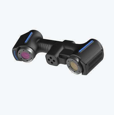
Selecting a workflow aligned with specific use case requirements, compliance standards, and existing operational systems helps industrial teams meet quality, traceability, and efficiency goals. INSVISION supports this approach through scanning systems designed to fit within structured workflows rather than replace them. The emphasis remains on process definition first, hardware selection second.
- What Is 3D Scanning? Principles, Workflow, and Industrial Applications 3D scanning is a digital measurement technology that converts the surface geometry of physical objects into 3D data. This entry covers its working principles, core parameters, industrial use cases, common misconceptions, and related technical…
- What Is a 3D Scanner? Types, Parameters, and Selection Criteria A 3D scanner captures three-dimensional surface data from physical objects and converts geometry, dimensions, and features into digital data for inspection, reverse engineering, and modeling.
- What Is 3D Scanning Accuracy? Accuracy, Repeatability, and Resolution Explained 3D scanning accuracy describes how closely scan data matches an object's actual geometry and dimensions. It is assessed through local accuracy, volumetric accuracy, stitching accuracy, repeatability, and resolution.
- What Is Point Cloud Data? Point Clouds, Meshes, and CAD Models in 3D Scanning Point cloud data is an important raw data format in 3D scanning. It consists of discrete 3D coordinate points that describe object surface geometry and support inspection, reverse engineering, modeling, and archiving.
Hangzhou Insvision Technology Co., Ltd.
Address: Building 1, No. 1399 Liangmu Road, Yuhang District, Hangzhou, Zhejiang 311121, China
Copyright © Hangzhou Insvision Technology Co., Ltd. All rights reserved.
Copyright © Hangzhou Insvision Technology Co., Ltd. All rights reserved.