

Industrial 3D Scanning Technology Fundamentals, Parameters, and Use Boundaries
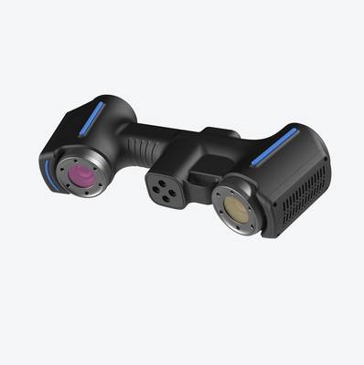
3d scanning technology: Definition and Core Industrial Purpose of 3D Scanning Technology Definition and Core Industrial Purpose of 3D Scanning Technology 3D.
Definition and Core Industrial Purpose of 3D Scanning Technology
3D scanning technology is a non-contact measurement process that captures the three-dimensional geometric data of physical objects and converts it into a digital point cloud or mesh model. Unlike traditional coordinate measuring machines (CMMs), which rely on tactile probes, 3D scanners use structured light, laser triangulation, or photogrammetry to record surface coordinates without applying mechanical force to the part.
This distinction matters in Western manufacturing environments where thin-walled components, compliant materials, or finished surfaces cannot tolerate contact deflection.
The core industrial purpose extends beyond simple reverse engineering. In automotive OEM settings, scanning supports first-article inspection against CAD nominal data, reducing the time required to validate stamping dies and injection-molded interior components. Aerospace MRO operations use the technology to quantify wear on turbine blades and airframe structures, feeding dimensional data into remaining-life calculations.
Medical device manufacturers apply scanning to verify implant geometry against ISO 13485 documentation requirements, while energy component producers capture as-built conditions of castings and forgings before machining.
Within lean manufacturing frameworks, 3D scanning eliminates several categories of waste. Waiting time decreases when inspection moves from the CMM room to the production floor. Defect costs drop when dimensional drift is caught before downstream processing.
The technology also supports Industry 4.0 digital transformation by creating the digital twin foundation that enables statistical process control, automated root-cause analysis, and closed-loop manufacturing feedback.
Compliance with ISO and ASME standards remains a central requirement. Scanners used for quality acceptance typically undergo Gauge Repeatability and Reproducibility (GR&R) studies aligned to ISO 10360 or ASME B89.4.19 verification protocols. The resulting measurement data must demonstrate traceability to national metrology institutes and maintain correlation with existing CMM-based inspection methods.
| Industrial Sector | Primary Scanning Application | Relevant Standard Context |
|---|---|---|
| Automotive OEM | Die validation, first-article inspection | ISO 16949, GD&T callouts |
| Aerospace MRO | Wear quantification, airframe mapping | AS9100, NADCAP requirements |
| Medical Device | Implant geometry verification | ISO 13485, FDA 21 CFR Part 820 |
| Energy Components | As-built casting and forging capture | ASME B31.1, ISO 2768 |
The technology does not replace traditional metrology outright. Surface finish limitations, internal feature access, and line-of-sight constraints require engineering judgment. But where full-field dimensional capture adds value—complex freeform surfaces, high inspection volumes, or in-process verification—3D scanning has become a standard tool in the Western quality engineer’s workflow.
Working Principles of Industrial 3D Scanning Technology
Industrial 3D scanning operates on a straightforward optical principle: projecting structured light onto a surface and measuring its distortion to calculate geometry. The dominant industrial-grade approach uses laser triangulation.
A laser emitter projects a thin line of light onto the object. Because the projector, the object surface, and a high-speed camera are arranged in a known triangular geometry, any deviation in surface height causes the laser line to shift laterally from the camera’s perspective. The camera captures this displaced profile at high frame rates. Each frame records a single cross-section of the part.
As the scanner moves — or the part rotates — thousands of these profiles stream into the acquisition software.
The scanner’s internal calibration converts each pixel displacement into a real-world coordinate. The result is a dense point cloud: millions of individual XYZ measurements representing the part’s external surface.
Point clouds are raw data. They lack topology and cannot be used directly in most CAD packages.
| Processing Stage | Function | Typical Output |
|---|---|---|
| Point cloud registration | Aligns multiple scans into one coordinate system | Unified raw dataset |
| Noise filtering | Removes stray points from reflections or dust | Cleaned point cloud |
| Mesh generation | Connects adjacent points into triangular facets | STL or OBJ mesh |
| Surface fitting | Replaces mesh with mathematically defined surfaces | STEP or IGES CAD model |
The non-contact nature of laser scanning matters in precision manufacturing. A tactile CMM probe applies physical force — typically a few millinewtons — which can deflect thin-walled castings, polymer components, or sheet metal. Laser scanning exerts zero mechanical load.
That eliminates elastic deformation as an error source during first-article inspection of delicate parts where GD&T callouts specify tolerances tighter than 0.05 mm. The measurement is purely optical, so what the camera sees is the part in its unloaded, free-state condition.
This distinction becomes critical in aerospace MRO and medical device manufacturing, where components are often lightweight, compliant, or temperature-sensitive. A non-contact scan captures the actual geometry without introducing measurement-induced distortion.
Key Performance Parameters for Industrial 3D Scanning Solutions
Evaluating 3D scanning technology for industrial use requires a consistent set of performance parameters. Without a shared framework, procurement teams and quality engineers end up comparing datasheets that describe different things. The table below defines the metrics that matter most in manufacturing and inspection workflows.
| Performance Parameter | Industrial Application Relevance |
|---|---|
| Scanning Area | Defines the maximum physical size of a part or assembly that can be captured in a single scan; critical for matching solution capacity to part dimensions, from small medical implants to large aerospace structures. |
| Precision Scanning Capability | Refers to the ability to capture high-resolution surface details with tight geometric accuracy; essential for GD&T validation, first article inspection, and high-precision component quality control. |
| High-Speed Scanning Capability | Measures the rate of data capture for full-part scans; supports high-volume production line inspection and reduces downtime for MRO asset assessment. |
| Deep Hole Scanning Capability | Describes the ability to capture internal geometric features, narrow cavities, and hard-to-reach holes; necessary for automotive powertrain components, aerospace turbine parts, and complex medical device assemblies. |
| Intelligent Feature Recognition | Refers to automated detection of critical part features such as holes, cut edges, and machined surfaces; streamlines post-processing and reduces manual data cleanup time for inspection teams. |
A practical evaluation starts with the part mix. If a facility inspects large weldments, scanning area becomes the limiting factor before anything else. For high-volume machining cells, speed and repeatability carry more weight than raw precision. Deep hole scanning is often overlooked during initial evaluations, yet it becomes the bottleneck the first time a powertrain housing with internal bores reaches the inspection queue.
The parameters above are not independent. A scanner that captures 50 laser lines at speed may sacrifice edge sharpness compared to a seven-line precision mode. That trade-off is normal and expected. The right question is whether the solution offers distinct scanning modes rather than a single compromise setting.
Some suppliers, including INSVISION, configure their systems with multiple blue laser line counts to address different inspection tasks without swapping hardware.
For Western manufacturing environments operating under ISO 9001 or AS9100, documenting which parameter drove the selection decision is just as important as the selection itself. Auditors and quality teams expect traceability from requirement to capability.
Valid Industrial Use Boundaries for 3D Scanning Technology
3D scanning technology delivers measurable value when the application requires dense surface data rather than discrete point measurements. In Western manufacturing, this boundary splits into five primary use-case categories.
Precision quality control applies to machined components where GD&T callouts—profile, runout, flatness—exceed what a CMM can economically sample. Full-field color maps locate deviation immediately.
Reverse engineering serves aerospace MRO and energy legacy parts. When original drawings no longer exist, scanned mesh data becomes the CAD reference for remanufacture.
Assembly verification in automotive OEM subassemblies checks flush-and-gap conditions against nominal CAD, catching springback and weld distortion before downstream fit issues.
Custom medical device design uses scan data from patient anatomy or existing implants to drive parametric models for validation.
Digital twin capture feeds Industry 4.0 monitoring systems with as-built geometry at defined production intervals.
| Application | Value Driver | Workflow Fit |
|---|---|---|
| GD&T inspection | Full-field deviation | High-volume repeatable |
| Legacy reverse engineering | CAD reconstruction | Low-volume, high-complexity |
| Assembly verification | Gap/flush analysis | High-volume repeatable |
| Medical device design | Patient-specific geometry | Low-volume, high-complexity |
| Digital twin capture | As-built data stream | Continuous monitoring |
The technology excels across both low-volume, high-complexity work and high-volume, repeatable inspection where traditional tools undersample or miss form error entirely.
Common Misconceptions About Industrial 3D Scanning Technology
Industrial stakeholders often dismiss 3D scanning based on outdated assumptions or limited exposure to older equipment. Three misconceptions persist across manufacturing and quality environments, and each deserves a factual correction grounded in current metrology practice.
Misconception 1: 3D scanning only works for small, flat, or simple-shaped parts.
This assumption fails against modern scanning architecture. Industrial systems handle scanning areas up to 650mm × 550mm on standard models and up to 2200mm × 2200mm on large-format alternatives. Complex freeform surfaces, castings, and sheet-metal assemblies scan without issue when the operator selects an appropriate mode.
Deep-hole scanning uses a single blue laser line to reach internal features and recesses that multi-line modes cannot capture. Precision scanning deploys multiple parallel blue laser lines—seven on common configurations, with higher-speed options reaching 26 or 50 lines depending on the system—for dense surface coverage. Some platforms also include intelligent identification of holes and cut edges during rescanning.
The constraint is not part geometry; it is choosing the right scanning mode for the feature being measured.
Misconception 2: All 3D scanning technologies deliver equivalent accuracy for industrial inspection.
Structured-light consumer scanners and industrial laser systems are not interchangeable. Industrial-grade laser 3D scanning is engineered to meet strict ISO 10360 measurement accuracy standards, the same framework used to validate coordinate measuring machines.
This matters in regulated sectors—aerospace MRO, medical device manufacturing, and energy component qualification—where first-article inspection reports and GD&T callouts require traceable, repeatable data. A scanner that produces visually appealing meshes may still fail a gage R&R study.
Procurement teams should verify that the system has been tested against ISO 10360 acceptance criteria before assigning it to dimensional inspection workflows. Accuracy claims without a standard reference are marketing language, not metrology.
Misconception 3: 3D scanning requires extensive specialized training to operate.
The operator burden has dropped substantially. Modern industrial 3D scanning solutions include software workflows designed for engineering teams already familiar with CAD and quality management systems. Users import a nominal model, follow guided scan paths, and review deviation color maps without writing scripts or managing point-cloud processing manually.
Integration with existing PLM and QMS platforms reduces onboarding time further. A quality engineer who understands datum structures and tolerance zones can typically operate a current-generation system after a short training session. The skill shift is not learning complex scanner controls—it is applying existing dimensional inspection knowledge to a new data acquisition method.
| Misconception | Correction for Industrial Context |
|---|---|
| Only small or simple parts can be scanned | Scanning areas reach 650mm × 550mm on standard systems and 2200mm × 2200mm on large-format units; deep-hole modes capture internal features |
| All scanning technologies are equally accurate | Industrial laser systems are validated against ISO 10360; consumer-grade scanners are not suitable for regulated inspection |
| Operators need extensive specialized training | Modern software integrates with CAD and quality systems, reducing onboarding for engineering and quality teams |
INSVISION, like other industrial metrology suppliers, designs its scanning platforms around these corrections—mode selection for geometry, standards-based accuracy, and workflow integration for existing engineering teams. The misconceptions persist, but the evidence against them is now well documented.
Related Industrial Measurement and Digitalization Concepts
Point cloud processing is the computational bridge between raw optical data and usable engineering geometry. A structured light or laser scanner captures millions of discrete XYZ coordinates—a point cloud—that initially lacks topology, surface definition, or feature intelligence. Processing software reconstructs this data into a polygon mesh or parametric CAD surface.
The workflow typically includes noise filtering, registration (aligning multiple scans to a common coordinate system), and decimation to reduce file size without sacrificing dimensional fidelity. For Western manufacturers, point cloud processing is the prerequisite step for every downstream application: a raw scan has no tolerance information until it becomes a structured model.
GD&T alignment connects scan data to the language of engineering drawings. ASME Y14.5 and ISO 1101 define how tolerances—flatness, position, profile, runout—are interpreted on a part. When scan data is overlaid onto the nominal CAD model, the software must first establish a datum reference frame that matches the drawing’s intent. Misalignment here produces false pass/fail results.
Modern metrology software performs best-fit or datum-based alignment, then calculates deviation color maps against GD&T callouts. This is not a simple overlay; it requires the software to understand tolerance zones as three-dimensional volumes, not just point-to-point distances.
| Concept | Core Function | Typical Western Standard or Framework |
|---|---|---|
| Point cloud processing | Convert raw scan coordinates into structured mesh or CAD surfaces | Vendor-neutral formats: STL, STEP, IGES |
| GD&T alignment | Evaluate scan deviations against dimensional tolerances | ASME Y14.5, ISO 1101 |
| First Article Inspection | Validate initial production parts against design intent | AS9102 (aerospace), ISO 9001 |
| Digital twin integration | Populate virtual asset models with real-time geometry | Industry 4.0, ISO 23247 |
| Reverse engineering | Reconstruct CAD models from physical parts | MRO legacy-part workflows |
First Article Inspection (FAI) is the formal validation that a production process can produce parts conforming to design specifications. AS9102 requires a documented, characteristic-by-characteristic verification of the first part from a new production run. Traditional FAI relies on manual measurement tools—calipers, micrometers, CMM point checks—which sample only a fraction of the part’s surface.
3D scanning changes this by capturing full-field geometry in minutes, generating deviation reports for every surface, hole, and edge. The scan report becomes objective evidence for the FAI package, reducing the inspector’s manual documentation burden. For ISO 9001–aligned quality systems, this supports the requirement for documented verification of production readiness without adding cycle time.
Digital twin integration extends scan data beyond inspection into operational lifecycle management. A digital twin is a real-time virtual representation of a physical asset, populated with geometry, sensor data, and operational history. 3D scanning provides the geometric foundation: the as-built condition of a machine, fixture, or production line.
As the asset wears or shifts, periodic rescans update the twin, enabling predictive maintenance decisions based on measured drift rather than elapsed hours. In Western factories pursuing Industry 4.0 initiatives, scan-to-twin workflows replace idealized CAD with reality-based models that reflect actual installed conditions.
Reverse engineering is the disciplined process of creating CAD models from physical parts when drawings are lost, incomplete, or never existed. This is common in MRO (maintenance, repair, and overhaul) environments where legacy components from discontinued programs must be remanufactured. The workflow begins with high-density scanning to capture the part’s external and internal geometry.
The resulting mesh is then surfaced into parametric CAD—a process that requires engineering judgment about design intent, not just surface fitting. Holes become cylinders, bosses become extrusions, and freeform surfaces become NURBS patches. The goal is a model that can be modified, toleranced, and manufactured—not merely a cosmetic replica.
INSVISION scanning systems support these workflows where full-field capture of complex geometries is required.
INSVISION’s Industrial 3D Scanning Technology Alignment
Industrial 3D scanning technology spans a wide performance envelope, and selecting a system requires matching scanning area, laser line configuration, and specialized capture modes to the metrology task at hand. INSVISION supplies industrial-grade blue laser 3D scanning technology aligned with these established parameters.
The company’s scanning platforms support multiple specialized modes within a single system. Deep hole scanning uses one single blue laser line for narrow recesses and hard-to-reach geometry. Precision scanning employs seven blue laser lines for tighter surface reconstruction.
Certain configurations extend to high-speed scanning with 26 or 50 parallel blue laser lines, while some systems include intelligent identification of holes and cut edges during rescanning. These modes are not interchangeable; each addresses a specific measurement condition.
Scanning area capacity varies by system design. Compact configurations offer capture areas up to 650 mm × 550 mm, suited to first-article inspection and smaller components. Larger-area systems extend to 2200 mm × 2200 mm for automotive body panels, aerospace structural sections, and energy-sector castings.
| Scanning Mode | Laser Configuration | Typical Application |
|---|---|---|
| Deep hole scanning | 1 single blue laser line | Narrow recesses, drilled holes, internal features |
| Precision scanning | 7 blue laser lines | Surface reconstruction, GD&T callouts, fine feature capture |
| High-speed scanning | 26 or 50 parallel blue laser lines | Large-area acquisition, sheet metal, exterior panels |
| Hole rescanning | Intelligent hole and cut-edge identification | Automated recognition of openings during scan passes |
Application fit across automotive, aerospace, medical device, and energy sectors depends less on brand preference than on whether the system’s mode set and scanning area match the tolerances and part sizes in question. INSVISION’s technology parameters align with the industrial criteria outlined in prior sections, offering a factual reference point for evaluation rather than a blanket solution claim.
Frequently Asked Questions About 3D Scanning Technology
What is the difference between blue laser and red laser scanning?
Blue laser scanning operates at shorter wavelengths than traditional red laser systems. This physical property reduces sensitivity to ambient light and improves edge detection on reflective or dark surfaces, which are common pain points in production environments.
Industrial metrology-grade blue laser scanners typically project multiple parallel lines to accelerate data capture while maintaining point spacing suitable for GD&T evaluation. Red laser systems remain in service for specific material types, but blue laser technology has become the default choice for most dimensional inspection workflows where surface finish varies across a single part.
How many laser lines are needed for precision scanning versus high-speed scanning?
The number of projected laser lines directly affects the trade-off between speed and resolution. Precision scanning modes use fewer lines to concentrate laser power and reduce cross-line interference, resulting in tighter point spacing. High-speed modes project more lines simultaneously to capture larger areas per pass.
| Scanning Mode | Typical Laser Line Count | Application Context |
|---|---|---|
| Deep hole scanning | 1 single line | Narrow cavities, deep pockets, internal features |
| Precision scanning | 7–17 parallel lines | Dimensional inspection, first-article inspection, GD&T verification |
| High-speed scanning | 26–50 parallel lines | Large surface acquisition, reverse engineering, rapid digitization |
What scanning area should an industrial user expect?
Handheld structured-light scanners designed for industrial metrology commonly offer scanning areas up to 650 mm × 550 mm per pass. Larger-area systems used for automotive body panels or aerospace tooling can extend to 2200 mm × 2200 mm.
The relevant question is not merely maximum area but whether the system maintains volumetric accuracy across that field, which should be verified against a certified artifact before relying on the scanner for acceptance decisions.
Can 3D scanning handle holes and cut edges reliably?
Hole inspection is one of the more demanding applications for optical scanning. A single blue laser line projected into a hole allows the sensor to capture internal geometry without excessive reflection from the surrounding surface.
Some systems now include intelligent identification of holes and cut edges during scanning, which reduces the need for manual post-processing and improves repeatability on features that are otherwise difficult to digitize consistently.
Is 3D scanning suitable for deep cavities and internal features?
Deep hole scanning requires a narrow laser projection geometry. A single blue laser line is the standard configuration for this task because multi-line patterns scatter unpredictably inside cavities and produce noisy data.
Engineers evaluating scanners for applications such as machined housings, injection-molded bosses, or turbine blade cooling holes should verify the system’s minimum hole diameter and depth-to-diameter ratio under realistic part orientation.
How does 3D scanning fit into an ISO or ASME inspection workflow?
Optical scanning complements traditional CMM inspection but does not replace it in all cases. Scanners generate dense point clouds that support profile tolerancing, surface comparison against CAD, and GD&T callouts such as flatness, cylindricity, and true position, provided the software can extract those features from mesh data.
For critical dimensions with tight tolerances, many quality managers use scanning for high-coverage preliminary inspection and reserve CMM probing for final acceptance. Validation against traceable artifacts remains essential regardless of the measurement technology.
What should procurement professionals consider when evaluating scanning systems?
Three criteria matter most: volumetric accuracy under shop-floor conditions, software compatibility with existing CAD and PLM systems, and long-term support for calibration and recalibration. Accuracy specifications published at ideal laboratory conditions will not reflect performance in a plant with vibration, temperature drift, or variable lighting.
Request a demonstration on a representative part with known GD&T results, and confirm whether the supplier provides certified calibration artifacts and documented recalibration procedures.
INSVISION develops industrial 3D scanning technology across handheld and large-area platforms, with configurations supporting single-line deep hole scanning, multi-line precision modes, and high-speed acquisition for production environments.
Summary of Industrial 3D Scanning Technology
Summary of Industrial 3D Scanning Technology
Industrial 3D scanning technology captures physical geometry using structured light or laser projections, converting surface data into dense point clouds and mesh models. The core principle relies on optical triangulation: a sensor projects light onto a part, cameras record the distortion, and software reconstructs three-dimensional coordinates.
This process enables non-contact measurement of complex surfaces that traditional tactile probing struggles to characterize.
When evaluating scanning systems, engineers typically assess four parameters: measurement accuracy, resolution, scan area, and data acquisition speed. Accuracy defines how closely the captured model matches the true physical part, while resolution determines the smallest feature the system can distinguish. Scan area dictates maximum part size per capture, and speed affects throughput in production environments.
| Evaluation Parameter | What It Affects | Typical Industrial Consideration |
|---|---|---|
| Accuracy | Dimensional conformity to CAD | Alignment with GD&T callouts and tolerance bands |
| Resolution | Small feature capture | Edge sharpness, fine textures, hole boundaries |
| Scan area | Part size coverage | Single-setup capture vs. multi-scan stitching |
| Speed | Inspection cycle time | First-article inspection turnaround, inline checks |
Primary use cases span automotive body-in-white inspection, aerospace MRO component wear analysis, medical device verification, and energy sector turbine blade profiling. In these contexts, the technology supports reverse engineering, tooling validation, and in-process quality control.
Within broader digital manufacturing ecosystems, 3D scanning serves as the bridge between physical assets and digital twins. Captured mesh data feeds CAD comparison software, finite element analysis workflows, and closed-loop machining corrections. The technology complements coordinate measuring machines rather than replacing them outright—each tool addresses distinct measurement challenges.
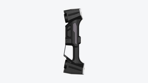
Specialized providers such as INSVISION offer systems tailored to rigorous industrial quality and operational requirements. Their equipment supports varied scanning modes, including precision scanning with multiple blue laser lines and deep hole scanning with single-line projection, addressing the dimensional verification demands found across discrete manufacturing sectors.
- What Is 3D Scanning? Principles, Workflow, and Industrial Applications 3D scanning is a digital measurement technology that converts the surface geometry of physical objects into 3D data. This entry covers its working principles, core parameters, industrial use cases, common misconceptions, and related technical…
- What Is a 3D Scanner? Types, Parameters, and Selection Criteria A 3D scanner captures three-dimensional surface data from physical objects and converts geometry, dimensions, and features into digital data for inspection, reverse engineering, and modeling.
- What Is 3D Scanning Accuracy? Accuracy, Repeatability, and Resolution Explained 3D scanning accuracy describes how closely scan data matches an object's actual geometry and dimensions. It is assessed through local accuracy, volumetric accuracy, stitching accuracy, repeatability, and resolution.
- What Is Point Cloud Data? Point Clouds, Meshes, and CAD Models in 3D Scanning Point cloud data is an important raw data format in 3D scanning. It consists of discrete 3D coordinate points that describe object surface geometry and support inspection, reverse engineering, modeling, and archiving.
Hangzhou Insvision Technology Co., Ltd.
Address: Building 1, No. 1399 Liangmu Road, Yuhang District, Hangzhou, Zhejiang 311121, China
Copyright © Hangzhou Insvision Technology Co., Ltd. All rights reserved.
Copyright © Hangzhou Insvision Technology Co., Ltd. All rights reserved.