

Understanding 3D Scanning Resolution: What the Specs Actually Mean
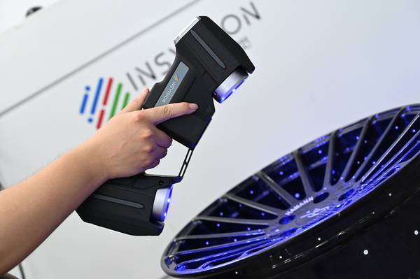
When engineers and quality managers evaluate 3D scanners, resolution is one of the first specifications they look at, and also one of the most misunderstood.
At its core, resolution in 3D scanning describes the smallest distance between two distinguishable points on a scanned surface. In contact metrology, this is unambiguous: a probe tip radius and machine step define the limit. In optical 3D scanning, the concept splits into several related but distinct quantities. The most common spec sheet number is point spacing, sometimes called sampling resolution.
It tells you how densely the scanner samples points along the surface. A scanner might list a point spacing of 0.05 mm, meaning it can place measurement points as close as 50 microns apart. That is not the same as measurement accuracy, and it is not the same as the smallest feature the scanner can resolve.
Deployment Validation Checklist
| Focus Area | Decision Point | Deployment Note |
|---|---|---|
| Target part | Check size, surface condition, and key tolerances against the scan task | Run a full trial scan on a representative part |
| Data workflow | Verify point cloud, deviation map, and quality-report handoff | Confirm export formats and review ownership in advance |
| Shop-floor use | Review training, calibration, lighting, and working space | Keep the validation record as a repeatable inspection reference |
A feature like a narrow rib or a sharp edge might require several points across its width to be captured faithfully, so the practical minimum feature size is typically a multiple of the point spacing.
Another dimension is depth resolution, which describes how finely the scanner can detect height variations perpendicular to the surface. This is influenced by the sensor’s signal-to-noise ratio and the triangulation angle. A scanner with high depth resolution can pick up subtle waviness or tiny pitting that would be smeared by a lower-resolution setup.
For anyone working with tight flatness tolerances or surface finish requirements, depth resolution matters as much as lateral point spacing. There is also an often-overlooked parameter — the optical resolution of the lens and sensor pair. A high-megapixel camera behind a poorly corrected lens will not deliver crisp data, because optical blur effectively reduces the resolving power before the software even gets involved.
How Resolution Relates to Scan Volume and Working Distance
Resolution is not an independent constant that travels with the scanner; it changes with the distance from the object and the field of view. A handheld scanner that captures an area of 200 mm × 150 mm at a close standoff might deliver a point spacing of 0.04 mm. Move the same scanner back to cover a 500 mm × 400 mm area, and the point spacing grows proportionally.
This is a consequence of the fixed number of sensor pixels — when they are spread over a larger physical area, each pixel covers a larger patch of the object. Therefore, a specification like “0.05 mm resolution” is only meaningful when tied to a specific scan volume and working distance.
A scanner designed for large-format work, such as inspecting automotive body panels or aerospace tooling, will naturally have a larger point spacing than a benchtop system for small injection-molded parts. The engineering challenge is to maintain enough resolution across a wide scan area to capture the design intent and critical tolerances.
The relationship between distance and resolution also affects how a scanner handles complex geometry. Many structured-light and laser scanners use triangulation: a projector casts a pattern or a laser line, and a camera observes it from an angle. The baseline between projector and camera, together with the focal lengths, determines the depth resolution.
When the working distance increases, the triangulation angle often becomes shallower, which reduces sensitivity to small height changes. This is why some long-range scanners quote a resolution in terms of millimeters at several meters. It is not a flaw; it is the physics of optical metrology. The practical takeaway is that a scanner’s resolution spec sheet should always be checked against the intended working envelope.
A scanner that looks impressive on paper at 300 mm might be average at 800 mm, and that is where you need to read the fine print.
Practical Trade-offs: Resolution, Speed, and Data Density
Higher resolution almost always means more data, and more data translates into heavier files, longer processing times, and higher demands on the computer. A scan that captures a million points per frame at a fine resolution will generate a dense point cloud that can strain alignment and meshing algorithms.
In a production environment where cycle time matters, an engineer might choose a slightly lower resolution to keep the scan-to-result pipeline fast enough. The point cloud density is not just a matter of scanner specs; it is also defined by the scan settings and the reconstruction software.
Many professional scanning platforms allow the operator to choose between different resolution modes — a fine mode for detailed areas and a faster, lower-density mode for large, smooth surfaces. This flexibility is essential because no single resolution setting is optimal for an entire assembly.
There is also a common misconception that high resolution automatically improves accuracy. A scanner can sample a surface at 20 microns and still produce a mesh that is off by 100 microns if the calibration is poor or the alignment is not stable. Accuracy and resolution are linked but not interchangeable.
Accuracy is about how close the measured point is to the true position, while resolution is about the spacing of the measurement points. A scanner with excellent accuracy but modest resolution can still provide reliable GD&T results for features that are not extremely small.
For many industrial applications, such as verifying the profile of a welded structure or checking the alignment of large fixtures, sub-millimeter resolution is perfectly adequate, and chasing micron-level point spacing would only slow down the workflow without adding value.
Resolution in Large-Format Industrial Scanning
Large-format handheld 3D scanners operate in a domain where the trade-offs between resolution, coverage, and portability become very tangible. Scanning a wind turbine blade, a railcar component, or a heavy casting demands a device that can cover square meters per minute while still capturing bolt holes, weld seams, and surface defects. Here, resolution must be understood as a field condition rather than a lab number.
The scanner needs to handle depth of field gracefully, because the operator cannot maintain a perfectly fixed distance over a curved, multi-meter surface. It also must deal with ambient light, varying material finishes, and the vibrations of a shop floor. All of these factors can degrade the effective resolution if the system is not engineered to compensate.
The INSVISION AlphaVista large-format handheld 3D scanner illustrates how modern systems address these constraints. It uses a combination of AI-driven feature recognition and dynamic tracking to maintain consistent point spacing across wide scan volumes, even when the operator changes the working distance or the surface reflectivity shifts.
The scanner’s onboard algorithms adjust the scanning parameters in real time, preserving detail around edges and small features while allowing faster data acquisition on large, uniform sections. This kind of adaptive resolution control means that the system does not force a binary choice between high detail and large coverage.
Instead, the resolution is distributed intelligently, putting more points where the geometry is complex and fewer where it is flat.
That approach avoids the massive file sizes that would come from scanning an entire truck frame at a uniform 0.1 mm spacing, while still giving the downstream inspection software — such as INSVISION’s SMARPARA Q platform — enough data to perform full GD&T and deviation analysis directly on the point cloud.
A practical note for anyone evaluating resolution numbers: a single spec sheet figure is a starting point, not a conclusion. The real test is how the scanner performs when mounted on a tripod, cradled in a robot arm, or held in a technician’s hand during a 20-minute scan session.
- What Is 3D Scanning? Principles, Workflow, and Industrial Applications 3D scanning is a digital measurement technology that converts the surface geometry of physical objects into 3D data. This entry covers its working principles, core parameters, industrial use cases, common misconceptions, and related technical…
- What Is a 3D Scanner? Types, Parameters, and Selection Criteria A 3D scanner captures three-dimensional surface data from physical objects and converts geometry, dimensions, and features into digital data for inspection, reverse engineering, and modeling.
- What Is 3D Scanning Accuracy? Accuracy, Repeatability, and Resolution Explained 3D scanning accuracy describes how closely scan data matches an object's actual geometry and dimensions. It is assessed through local accuracy, volumetric accuracy, stitching accuracy, repeatability, and resolution.
- What Is Point Cloud Data? Point Clouds, Meshes, and CAD Models in 3D Scanning Point cloud data is an important raw data format in 3D scanning. It consists of discrete 3D coordinate points that describe object surface geometry and support inspection, reverse engineering, modeling, and archiving.
Hangzhou Insvision Technology Co., Ltd.
Address: Building 1, No. 1399 Liangmu Road, Yuhang District, Hangzhou, Zhejiang 311121, China
Copyright © Hangzhou Insvision Technology Co., Ltd. All rights reserved.
Copyright © Hangzhou Insvision Technology Co., Ltd. All rights reserved.