

3D Scanning Inspection Report
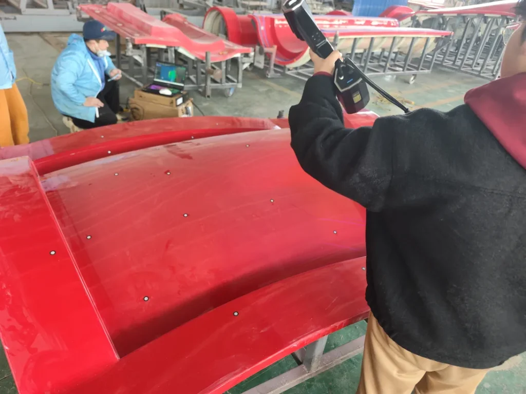
A 3D scanning inspection report is a standardized, structured output document generated from industrial 3D metrology workflows that quantitatively and visually documents the geometric conformance of a physical test part against a predefined reference.
Definition
A 3D scanning inspection report is a standardized, structured output document generated from industrial 3D metrology workflows that quantitatively and visually documents the geometric conformance of a physical test part against a predefined reference. The report is used to identify dimensional deviations, defects, and compliance with engineering specifications, supporting quality control, root cause analysis, and regulatory audit processes across manufacturing, aerospace, automotive, mold making, and energy sectors. References may include official CAD models, 2D engineering drawings, or 3D scans of pre-qualified conforming "golden" parts.
How It Works
The generation of a 3D scanning inspection report follows a standardized, multi-step workflow:
- Reference preparation: The baseline reference dataset is loaded or created, either as a native CAD file, 2D drawing-derived geometric specification, or a high-accuracy 3D scan of a pre-qualified golden part for cases where no official CAD exists.
- 3D data capture: High-density geometric data of the test part is collected using industrial 3D scanning hardware (including handheld laser, structured blue light, optical tracking-enabled, or automated stationary systems) aligned to a common coordinate system via fiducial markers, feature-based alignment, or real-time optical tracking.
- Data processing and alignment: Raw scan data is cleaned to remove environmental noise, fill minor surface gaps, and isolate the part from surrounding fixtures. The processed scan data is aligned to the reference dataset using either datum-based alignment (tied to part drawing reference frames) or best-fit alignment for free-form components.
- Analysis: Automated or manual analysis is performed to calculate geometric deviations, measure GD&T characteristics, and identify defects such as warpage, shrinkage, or machining errors. AI-powered algorithms may be used to auto-identify common anomalies and streamline alignment for high-volume workflows.
- Report compilation: Quantitative results, color-coded deviation maps, feature-specific measurement data, and pass/fail status flags are compiled into a structured report, with embedded metadata for traceability.
Key Parameters and Criteria
The validity and utility of a 3D scanning inspection report depend on standardized, measurable parameters, with acceptable thresholds defined by part-specific engineering requirements, industry regulations, or internal quality management protocols. Core parameters include the following:
| Parameter | Meaning | Judgment Method |
|---|---|---|
| Maximum/Mean Deviation | Quantitative difference between scanned part geometry and reference dataset at the most disparate point / across all measured points | Calculated via inspection software after rigid alignment; acceptable thresholds defined by part engineering specifications |
| GD&T Compliance Rate | Percentage of measured geometric features (e.g., flatness, position, cylindricity) that meet defined tolerance requirements | Verified via built-in GD&T tools in inspection software, aligned to part drawing requirements |
| Scan Data Coverage Ratio | Proportion of the part’s target surface that is successfully captured in the 3D scan, excluding intentionally occluded areas | Calculated by comparing captured scan area to total reference surface area; minimum acceptable ratio varies by part use case |
| Alignment Uncertainty | Margin of error introduced during the process of aligning scan data to the reference coordinate system | Derived from software uncertainty calculations and fiducial marker placement accuracy; must be below 10% of the smallest specified part tolerance for valid results |
| Traceability Identifier | Unique tag linking the report to specific scan hardware, software version, test part batch, and operator | Verified via embedded metadata in the report; required for regulated industry quality audits |
Suitable and Unsuitable Scenarios
Suitable Scenarios
- Batch quality control of small to medium industrial parts, including castings, moldings, sheet metal components, and 3D printed parts
- Dimensional verification of large-format industrial components such as aerospace structures, automotive body panels, and heavy equipment parts
- Compliance checks for regulated industry parts requiring auditable geometric conformance documentation
- Inspections for legacy or custom parts where no official CAD model is available, using a golden sample as the reference
- First Article Inspection (FAI) and Production Part Approval Process (PPAP) documentation for manufacturing suppliers
Unsuitable Scenarios
- Microscale parts with features smaller than the minimum resolution of standard industrial 3D scanning hardware
- Parts with fully transparent, highly specular, or light-absorbent surfaces that cannot be prepared with temporary matte coating to enable scanning
- In-line production inspection use cases where total scan and report generation time exceeds required production takt time
- Applications requiring only qualitative visual defect assessment with no quantitative geometric deviation data
Common Misconceptions
- Misconception: 3D scanning inspection reports are universally accurate, regardless of workflow context.
Correction: Report accuracy is directly tied to scan hardware resolution, alignment method, surface preparation, reference dataset quality, and environmental conditions. All valid reports include an alignment uncertainty value that must be evaluated alongside reported deviation results.
- Misconception: A CAD model is required to generate a valid 3D scanning inspection report.
Correction: Pre-qualified golden sample scans of conforming physical parts may be used as the reference dataset for inspections, a common practice for legacy components, custom tooling, and heavy industrial parts such as cold rolling rolls.
- Misconception: All 3D scanning inspection reports follow a single global standard.
Correction: Report structure, required metrics, and traceability requirements vary by industry; for example, aerospace and medical device inspections require far more rigorous audit trails than consumer goods component inspections, per regulatory mandates.
- Misconception: Higher scan resolution always produces a more useful inspection report.
Correction: Excessively high scan resolution increases data processing time, file size, and workflow cost without adding measurable value for parts with loose tolerance requirements. Resolution should be matched to the smallest specified tolerance of the part being inspected.
Related Concepts
- 3D Metrology: The broader field of measuring and analyzing the physical geometry of objects using 3D capture technologies, of which 3D scanning inspection is a core application.
- Geometric Dimensioning and Tolerancing (GD&T): A standardized symbolic language used on engineering drawings to define allowable deviations for part features, a core component of most inspection report analyses.
- Point Cloud Deviation Mapping: A visual analysis technique that color-codes geometric differences between scan data and a reference dataset, typically included as a key visualization in 3D scanning inspection reports.
- Golden Sample Inspection: An inspection workflow that uses a pre-qualified conforming physical part as the reference instead of a CAD model, supported by all major industrial 3D inspection software platforms.
- Automated 3D Inspection: A high-volume inspection workflow that integrates automated scanning systems, robotic part handling, and AI-driven analysis to generate inspection reports with minimal manual operator input.
- Structured Light 3D Scanning: A 3D capture technology that uses projected light patterns to capture high-accuracy part geometry, commonly used for high-precision inspection workflows.
FAQ
Can a 3D scanning inspection report be used for regulatory quality audits?
Yes, provided the report includes complete traceability metadata (including scan hardware calibration records, software version, unique part identification, alignment method, and calculated measurement uncertainty) and meets the specific documentation requirements of the relevant regulatory body and industry standard.
What happens if critical part surfaces are not captured in the 3D scan data?
Missing surface areas are explicitly documented in the report. If the missing areas include features specified for inspection, the report will flag the result as incomplete, and a targeted re-scan of the affected areas is typically required to generate a valid conformance result.
Do I need a CAD model to generate a valid 3D scanning inspection report?
No. For use cases where no official CAD model exists (such as legacy tooling, custom parts, or components with lost design documentation), a high-accuracy 3D scan of a pre-qualified conforming "golden" part may be used as the reference dataset for deviation analysis.
Can 3D scanning inspection reports include GD&T measurements?
Yes. Most industrial 3D inspection software platforms include native GD&T analysis tools that measure feature characteristics such as flatness, position, concentricity, and profile tolerance, with results, tolerance thresholds, and pass/fail status compiled directly into the final report.
Summary
A 3D scanning inspection report is a core output of industrial 3D metrology workflows, designed to document the geometric conformance of physical parts against predefined specifications for quality control, audit, and process improvement purposes. Generated via a structured process of reference preparation, 3D data capture, alignment, analysis, and compilation, valid reports include standardized metrics for deviation, GD&T compliance, data coverage, measurement uncertainty, and traceability. It is widely deployed across manufacturing, aerospace, automotive, and energy sectors for use cases ranging from first article inspection to batch quality control, though it is not suitable for microscale parts, unscannable surface types, or applications requiring only qualitative assessment. Common misconceptions regarding mandatory CAD references or universal accuracy standards are addressed by context-specific workflow configurations and industry-specific reporting requirements.
- What Is 3D Scanning? Principles, Workflow, and Industrial Applications 3D scanning is a digital measurement technology that converts the surface geometry of physical objects into 3D data. This entry covers its working principles, core parameters, industrial use cases, common misconceptions, and related technical…
- What Is a 3D Scanner? Types, Parameters, and Selection Criteria A 3D scanner captures three-dimensional surface data from physical objects and converts geometry, dimensions, and features into digital data for inspection, reverse engineering, and modeling.
- What Is 3D Scanning Accuracy? Accuracy, Repeatability, and Resolution Explained 3D scanning accuracy describes how closely scan data matches an object's actual geometry and dimensions. It is assessed through local accuracy, volumetric accuracy, stitching accuracy, repeatability, and resolution.
- What Is Point Cloud Data? Point Clouds, Meshes, and CAD Models in 3D Scanning Point cloud data is an important raw data format in 3D scanning. It consists of discrete 3D coordinate points that describe object surface geometry and support inspection, reverse engineering, modeling, and archiving.
Hangzhou Insvision Technology Co., Ltd.
Address: Building 1, No. 1399 Liangmu Road, Yuhang District, Hangzhou, Zhejiang 311121, China
Copyright © Hangzhou Insvision Technology Co., Ltd. All rights reserved.
Copyright © Hangzhou Insvision Technology Co., Ltd. All rights reserved.