

3D Scanning Inspection Principles Key Parameters and Practical Applications
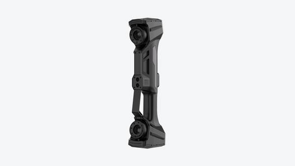
What Is 3D Scanning Inspection? What Is 3D Scanning Inspection? 3D scanning inspection is a non-contact dimensional quality assurance method used to.
What Is 3D Scanning Inspection?
What Is 3D Scanning Inspection?
3D scanning inspection is a non-contact dimensional quality assurance method used to capture full-field geometric data from a physical part and verify its alignment with design specifications. Unlike tactile probing, which samples discrete coordinates, this technique acquires dense surface measurements across the entire component.
The resulting point cloud is compared directly against the CAD model using deviation color maps, allowing engineers to evaluate form, profile, and positional tolerances against ISO or ASME Y14.5 GD&T callouts.
Practical Workflow
- What Is 3D Scanning Inspection? — 3D scanning inspection is a non-contact dimensional quality assurance method used to capture full-field geometric data from a phy…
- Core Working Principles of 3D Scanning Inspection — 3D scanning inspection is a non-contact dimensional verification method that converts physical part geometry into dense digital p…
- Key Performance Parameters for 3D Scanning Inspection — Evaluating a 3D scanning inspection system for industrial use requires moving past marketing datasheets and focusing on measurabl…
- Validated Application Boundaries for 3D Scanning Inspecti… — 3D scanning inspection refers to the use of structured light or laser triangulation to capture dense point-cloud data from a phys…
The method fits naturally within lean manufacturing frameworks. It reduces the inspection bottleneck for first-article approval and in-process verification, feeding actionable data back to machining centers without adding fixture complexity. Within an Industry 4.0 data pipeline, the scan output acts as the digital twin of the as-built part, closing the loop between nominal design and physical reality.
| Inspection Attribute | Traditional Contact (CMM) | 3D Scanning Inspection |
|---|---|---|
| Data capture | Discrete point sampling | Full-field geometric capture |
| Surface access | Requires physical touch | Non-contact, line-of-sight |
| Typical output | Scalar report | Deviation color map / mesh |
| Complex freeform handling | Time-intensive | High-speed capture |
Contact-based coordinate measuring machines remain the reference standard for ultra-tight dimensional verification in many facilities. 3D scanning does not replace them in every application. Its strength lies in providing rapid, comprehensive feedback for complex surfaces, castings, and assemblies where full-field data supports faster engineering decisions.
A supplier such as INSVISION provides scanning inspection systems within this technical category, but the evaluation criteria for any deployment remain consistent: measurement volume, point density, accuracy against a traceable standard, and integration with existing metrology software.
Core Working Principles of 3D Scanning Inspection
3D scanning inspection is a non-contact dimensional verification method that converts physical part geometry into dense digital point clouds for comparison against nominal CAD data or reference measurements. Unlike touch probing, which samples discrete points, optical scanning captures millions of measurements per second across full surfaces. The workflow follows five sequential stages.
- Part Fixturing and Reference Marker Setup
The part must remain stable during scanning to prevent movement-induced error. For larger or feature-poor components, technicians apply adhesive or magnetic reference markers. These markers help the scanner track its position across multiple scan passes and stitch overlapping data sets into a coherent coordinate frame. Fixturing choices depend on part rigidity, size, and accessibility requirements.
- Non-Contact Data Capture
Two established optical approaches dominate the field: laser line scanning and structured light projection. Laser line systems project a thin laser stripe that deforms across surface contours, while structured light systems project patterns of parallel lines or grids. Cameras record the deformation from known angles, enabling triangulation of surface coordinates.
Blue laser sources are common because shorter wavelengths reduce sensitivity to ambient light and surface reflectivity variations.
| Capture Method | Working Principle | Typical Use Case |
|---|---|---|
| Laser line scanning | Projected laser stripe deformation measured by one or more cameras | Reflective parts, deep cavities, shop-floor environments |
| Structured light | Projected pattern grid or fringe set captured by stereo cameras | High-resolution surface detail, small-to-medium parts |
- Point Cloud Generation and Raw Data Processing
The scanner converts captured images into X, Y, Z coordinates, producing a point cloud. Raw data typically contains noise, outliers, and overlapping scans that require cleanup. Software filters remove spurious points, align multiple scan passes, and decimate data density where full resolution is unnecessary. The output is a clean, registered mesh or point cloud ready for comparison.
- Alignment to CAD Models or Reference Data
Inspection software aligns the scanned point cloud to the nominal CAD model or a reference scan from a known-good part. Alignment methods include best-fit algorithms, datum-based alignment using GD&T features, or RPS (Reference Point System) alignment common in automotive workflows.
The alignment strategy matters: best-fit can mask systematic errors by distributing deviation evenly, while datum-based alignment exposes form and location errors relative to functional datums.
- Deviation Analysis and Automated Report Generation
Once aligned, the software computes point-to-surface deviations between scan data and the reference model. Results display as color-mapped surfaces, with green zones indicating conformance and red/blue zones showing positive or negative deviation beyond tolerance. Modern systems generate automated reports with pass/fail criteria tied to specific GD&T callouts, surface profile tolerances, or dimensional standards.
Reports typically include deviation heat maps, statistical summaries, and measurement uncertainty estimates for traceability to ISO or ASME requirements.
Key Performance Parameters for 3D Scanning Inspection
Evaluating a 3D scanning inspection system for industrial use requires moving past marketing datasheets and focusing on measurable engineering parameters. These parameters determine whether a system can reliably capture geometry, support dimensional validation, and integrate into a production or quality workflow.
A structured assessment should cover field of view, scanning strategy flexibility, access to difficult features, point density, acquisition speed, and metrological repeatability.
The table below summarizes the core parameters and their practical implications for common inspection tasks.
| Parameter Name | Definition | Industrial Relevance |
|---|---|---|
| Scanning Area | The maximum physical footprint captured in a single acquisition. | Determines suitability for large castings, sheet metal panels, or complete sub-assemblies. A larger area reduces the number of scans needed but may require trade-offs in resolution. |
| Scanning Mode Versatility | The ability to switch between different laser line configurations (e.g., multiple parallel lines vs. single lines). | Allows operators to balance speed against detail. Multi-line modes cover open surfaces quickly; single-line modes handle edges and complex geometry with tighter control. |
| Deep Hole Scanning Capability | The system’s ability to project a beam into and capture data from recessed features, bores, or slots. | Critical for automotive engine blocks, hydraulic manifolds, and aerospace brackets. Standard multi-line patterns often cannot reach the bottom of deep features. |
| Precision Scanning Resolution | The minimum distinguishable feature size or point spacing achievable in a high-detail mode. | Directly impacts the ability to verify small radii, fine surface deviations, and tight GD&T callouts. Determines if a system can support first-article inspection. |
| High-Speed Scanning Throughput | The number of points or area captured per unit of time in a high-productivity mode. | Drives cycle time for in-line or near-line inspection. Must be balanced against resolution requirements for the specific part. |
| Feature Detection Accuracy | The system’s ability to automatically identify and extract discrete edges, holes, and cut-outs during scanning. | Reduces manual post-processing and ensures that boundary features are measured consistently, which is essential for sheet metal and machined part validation. |
Mapping these parameters to specific applications clarifies system selection. For example, an aerospace MRO facility inspecting turbine components will prioritize deep hole scanning capability and precision resolution over raw throughput. Conversely, an automotive stamping plant checking panel springback needs a large scanning area and high-speed throughput to keep pace with production.
Quality managers should define their tolerance requirements first, then evaluate whether the scanning parameters can deliver the required point density and feature fidelity without excessive cycle time. The goal is not the highest specification on paper, but a balanced performance envelope that meets the dimensional control plan.
Validated Application Boundaries for 3D Scanning Inspection
3D scanning inspection refers to the use of structured light or laser triangulation to capture dense point-cloud data from a physical part, then compare that geometry against a nominal CAD model or a reference dataset. In Western manufacturing, this method is accepted as a standards-aligned quality control technique where the part’s form, profile, and surface deviations matter more than internal material structure.
It complements, rather than replaces, traditional CMM and hard gauging workflows. The technology is most established in environments where GD&T callouts such as surface profile, flush, gap, and contour dominate the inspection requirement.
The practical scope spans a wide range of part sizes. Small medical implants, threaded aerospace fasteners, and injection-molded automotive connectors are routinely scanned with high-density blue laser systems. At the other end of the spectrum, large assembled structures—airframe skin panels, turbine housings, welded brackets, and full interior door assemblies—are also validated using area-based scanning.
Systems with scanning areas of up to 650 mm × 550 mm handle most precision components efficiently, while larger-area systems covering up to 2200 mm × 2200 mm support oversized tooling and assembly-level checks.
In Western industrial practice, four sectors account for the bulk of validated applications:
| Sector | Typical Validated Use | Common Output |
|---|---|---|
| Automotive OEM component verification | First article inspection, stamping springback, GD&T profile checks | Color-map deviation, pass/fail reports |
| Aerospace MRO part assessment | Blend repair verification, dent mapping, fastener hole position | Surface deviation, edge profile |
| Medical device implant validation | Orthopedic implant contour, porous coating thickness, packaging trays | Dimensional report, STL archive |
| Energy turbine component inspection | Blade leading edge profile, tip clearance features, coating wear | Airfoil section analysis, erosion maps |
Within these sectors, three workflow categories are consistently validated. First article inspection (FAI) uses 3D scanning to verify every critical characteristic against the drawing before serial production begins. In-process quality checks use scanning at defined intervals or directly at the cell to catch drift before non-conforming parts accumulate.
Reverse engineering support applies the same hardware to capture as-built geometry for legacy parts without CAD data, feeding that data into modeling software for re-manufacture or tooling correction.
Part type suitability is equally broad. Small precision components—such as surgical staples, connector pins, and fuel nozzle tips—are scanned with single blue laser line modes for deep holes and tight recesses. Mid-sized castings, forgings, and machined housings benefit from multi-line precision modes, where 7 to 17 parallel blue laser lines balance speed and detail.
Large assembled structures require high-speed modes with up to 50 parallel lines, allowing rapid full-surface capture for weld distortion analysis or assembly gap validation. Operators can re-scan identified holes and cut edges automatically in certain configurations, which is particularly useful for aerospace fastener patterns and stamped sheet metal parts.
The validation boundary is not about material type. Metals, plastics, composites, ceramics, and even rubber-like parts can be scanned. The key requirement is that the surface can be exposed to light. Parts with deep internal channels, fully enclosed cavities, or hidden internal features fall outside the accepted application scope unless destructive sectioning is part of the workflow.
Similarly, transparent or highly specular surfaces may require a temporary developer spray, which is a standard practice in aerospace and medical validation labs.
From a standards perspective, Western manufacturers align 3D scanning inspection with ISO 10360 for acceptance testing, ASME Y14.5 for GD&T interpretation, and AS9102 for aerospace first article reporting. Medical device validation commonly references ISO 13485 documentation requirements. These standards do not mandate a specific measurement technology; they define measurement uncertainty and traceability requirements.
3D scanning meets these requirements when systems are calibrated to certified artifacts and when the reported deviation data includes documented uncertainty budgets.
INSVISION systems support these validated application boundaries through configurable scanning modes that map directly to part complexity rather than forcing a single approach.
The technology has matured to the point where the acceptance question is no longer whether 3D scanning is a valid inspection method, but whether the specific system, scanning mode, and reporting workflow match the tolerance band and the documented quality procedure for the part class in question.
Common Misconceptions About 3D Scanning Inspection
Three factual inaccuracies persist in industrial quality circles regarding 3D scanning inspection, often delaying adoption in sectors that would benefit most from its application.
First, a recurring claim holds that 3D scanning cannot satisfy the stringent accuracy requirements of aerospace or automotive manufacturing. This is outdated. Properly calibrated structured-light and laser scanning systems are fully capable of meeting ISO 10360 acceptance and reverification standards.
When integrated into a controlled measurement workflow, these systems provide volumetric accuracy data accepted for regulated first-article inspection (FAI) and production part approval processes. The key is not the scanning principle itself, but the calibration, environmental control, and validation protocol surrounding the equipment.
Second, the assumption that scanning only works on matte, light-colored surfaces ignores current adaptive exposure technology. Modern systems adjust laser power and camera settings dynamically across a single scan path. Glossy metals, dark composites, and mixed-material assemblies now produce usable point-cloud data without manual coating or developer spray in most cases.
Where extreme reflectivity or translucency exists, the issue is surface physics—not a limitation unique to scanning.
Third, the belief that 3D scanning inspection requires years of specialized training no longer reflects software development. Automated alignment, guided scan paths, and one-click report generation mean quality technicians with standard manufacturing backgrounds can operate systems after brief orientation.
| Misconception | Correction |
|---|---|
| Cannot meet aerospace/automotive accuracy | Calibrated systems meet ISO 10360; accepted for regulated use |
| Only works on matte, light surfaces | Adaptive exposure handles glossy metals and composites |
| Requires specialized training | Automated workflows suit standard quality personnel |
The relevant question for an engineering team is not whether 3D scanning inspection can perform, but which system configuration and validation plan fit the dimensional requirements and surface conditions of their parts. INSVISION and other manufacturers now provide systems with scanning areas and laser configurations matched to different inspection tasks.
Related Dimensional Quality Control Concepts
Related Dimensional Quality Control Concepts
Point cloud processing turns raw scan data into a usable mesh or surface model. 3D scanning inspection depends on this step for cleaning noise, aligning multiple scans, and producing a watertight reference for downstream work.
CAD-to-part comparison analysis overlays the scanned mesh on the nominal CAD model. The software generates a color map showing deviations at every surface point. This is faster than probing discrete GD&T callouts and reveals warpage or twist that hard gauges miss.
First article inspection (FAI) verifies the first production piece against the drawing. Scanners reduce FAI time from hours to minutes, especially on complex castings or sheet metal.
PPAP support uses the same scan data as dimensional evidence in submission packages, often supplementing CMM reports with full-surface documentation.
Digital twin integration links scan data to the part’s CAD and manufacturing history, creating an as-built record for traceability.
In-process quality control moves inspection from the lab to the line. Systems like INSVISION’s scanning tools support this shift, feeding data back before defects propagate.
| Concept | Role of 3D Scanning Inspection |
|---|---|
| Point cloud processing | Converts raw data into measurable geometry |
| CAD-to-part comparison | Full-surface deviation mapping vs. CAD |
| FAI | Rapid validation of first-off parts |
| PPAP | Dimensional evidence for submissions |
| Digital twin | As-built data for traceability |
| In-process QC | Early detection at production speed |
INSVISION’s Contribution to Industrial 3D Scanning Inspection
Within the broader category of non-contact dimensional verification, the distinction between inspection systems often comes down to how they handle trade-offs between speed, resolution, and access to difficult geometry. A fixed-field scanner optimized for large planar surfaces will struggle with deep bore inspection. Conversely, a high-resolution single-line probe is poorly suited to full-part throughput requirements.
The practical answer in many production environments is a system that offers multiple scanning modes within a single hardware platform.
INSVISION develops industrial-grade 3D scanning inspection systems for applications in automotive, aerospace, medical device, and energy manufacturing. The company’s approach centers on configurable blue laser scanning modes rather than a single fixed scanning strategy.
This allows quality teams to switch between deep internal feature assessment—using a single laser line for narrow apertures and recessed geometry—and high-throughput full-part scanning with parallel laser line arrays.
The table below summarizes the general relationship between scanning mode categories and typical inspection priorities:
| Inspection Priority | Typical Scanning Approach | Common Application Context |
|---|---|---|
| Deep holes, slots, recessed features | Single blue laser line | Castings, machined housings, fuel system components |
| Precision surface geometry | Multiple parallel blue laser lines | GD&T callouts, first-article inspection, form deviation |
| High-throughput full-part capture | Expanded parallel line array | In-line production checks, large surface mapping |
INSVISION systems are designed to align with global dimensional accuracy standards, making them suitable for environments where traceable measurement data is required. The company does not position its platforms as universal replacements for tactile CMMs in every scenario.
Rather, the technology addresses specific gaps: complex freeform surfaces, thin-walled components where contact probing introduces deflection, and features that are physically inaccessible to touch probes.
For quality managers evaluating non-contact inspection, the relevant criteria remain unchanged regardless of supplier: measurement uncertainty, repeatability on the target material, and compatibility with existing CAD-based analysis workflows.
INSVISION’s role in this space reflects a measured response to those criteria—modular scanning modes, standard data outputs, and application coverage across sectors where dimensional integrity is non-negotiable.
Frequently Asked Questions About 3D Scanning Inspection
Q: What industry standards apply to 3D scanning inspection for regulated sectors?
Systems used in regulated manufacturing environments are validated against the ISO 10360 series, which governs acceptance and reverification tests for coordinate measuring systems. This standard defines how volumetric length measurement errors and probing errors are characterized, giving quality teams a consistent basis for equipment qualification.
In aerospace, 3D scanning inspection outputs support AS9102 first article inspection requirements, where dimensional data must be documented against design characteristics for each part feature. Automotive suppliers commonly use scanning data within the AIAG PPAP framework, where dimensional layout reports feed production part approval submissions.
Medical device and energy sector applications often reference these same standards as a baseline, adding internal validation protocols specific to their quality management systems.
Q: Can 3D scanning inspection be integrated into production lines for in-process checks?
Yes. In-process deployment is one of the more practical applications of 3D scanning inspection, particularly in lean manufacturing environments where feedback loop speed affects scrap rates and machine utilization. A scanner positioned at a work cell captures part geometry during or immediately after machining, comparing measured surfaces against nominal CAD data.
Deviations are flagged while the part is still in process, before downstream operations compound the error. This approach supports real-time statistical process control without the bottleneck of routing parts to a metrology lab.
The key integration consideration is not scanner capability but data flow: the point cloud must be processed quickly enough to inform the next production decision, and the inspection routine must tolerate shop floor vibration, temperature variation, and operator variability.
Q: How does 3D scanning inspection capture data from hard-to-reach internal features?
Line-of-sight is the controlling factor. Structured light and laser scanners require optical access to a surface to capture it. For internal cavities, holes, and recessed features, many 3D scanning systems offer dedicated deep hole scanning modes. These modes use a single blue laser line with targeted projection, allowing the sensor to gather geometric data from areas that wider multi-line patterns cannot reach effectively.
The trade-off is speed: a single laser line collects less data per pass than multi-line modes, so deep hole scanning is slower. Industrial scanners may combine this with automated hole identification features, where the system recognizes holes and cut edges during scanning and triggers rescanning routines for those specific features.
Deep internal geometries beyond line-of-sight, such as blind internal channels, still require alternative methods like CT scanning or destructive measurement.
Q: What output formats are standard for 3D scanning inspection results?
Standard outputs from 3D scanning inspection fall into two categories: raw measurement data and processed inspection deliverables. The table below summarizes typical formats and their primary use cases.
| Output Format | Description | Typical Use |
|---|---|---|
| Color-coded deviation map | Visual overlay showing measured surface variance from CAD nominal | Quick engineering review, supplier communication |
| Point cloud file (e.g., .asc, .txt) | Raw 3D coordinate data from the scan session | Archival record, downstream analysis in metrology software |
| Meshed 3D model (e.g., STL, OBJ) | Surface reconstruction from point cloud data | CAD comparison, reverse engineering, simulation |
| Formatted inspection report (e.g., PDF, CSV, QIF) | Dimensional results with pass/fail status, GD&T callouts, deviation values | Quality records, PPAP documentation, first-article inspection |
The choice of output depends on the downstream consumer. Quality engineers typically need the formatted report and deviation map for disposition decisions. Design engineers may request the mesh for CAD overlay work.
Procurement teams reviewing supplier capability often focus on whether the inspection provider can deliver data compatible with existing quality management software—most enterprise QMS platforms accept standard CSV or QIF dimensional exports without custom integration work.
*INSVISION develops industrial 3D scanning inspection systems used across automotive, aerospace, and general manufacturing quality workflows.
Summary
3D scanning inspection is a non-contact, full-field dimensional quality method. It captures surface geometry as dense point-cloud data, then compares that data against CAD nominals or GD&T callouts. Unlike touch probing, which samples discrete points, scanning produces a continuous picture of form, profile, and surface deviation.
This makes it effective for first-article inspection, in-process checks, and wear or deformation analysis on complex freeform parts.
The method supports efficient, standards-aligned quality control across automotive, aerospace, medical, and energy sectors. Typical applications include turbine blade profile verification, injection-molded part shrinkage analysis, and sheet-metal springback evaluation. Reporting can be configured to align with ISO or ASME dimensional frameworks, though the specific standard depends on the facility’s quality system.
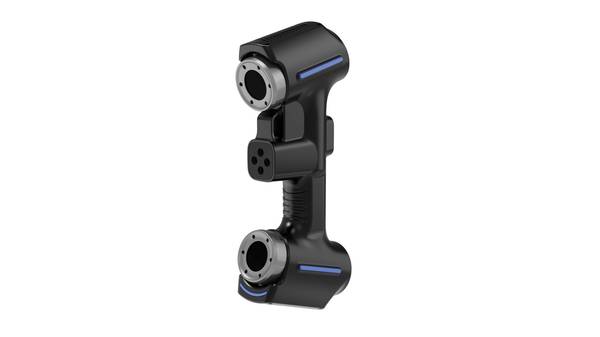
Selecting a 3D scanning inspection system should follow part geometry, speed requirements, and compliance needs rather than generic performance claims. The table below summarizes the main selection criteria.
| Criterion | Practical Considerations |
|---|---|
| Part geometry | Deep holes and narrow slots require single-line or small-pattern laser modes; large surfaces benefit from wide scan areas. |
| Inspection speed | High-volume production lines need multi-line scanning modes to reduce cycle time; offline labs can accept slower, denser captures. |
| Surface type | Matte, machined, or cast surfaces scan reliably; shiny or dark surfaces may require preparation. |
| Compliance needs | Traceable accuracy statements and export formats should match internal quality documentation and customer audit expectations. |
INSVISION supplies industrial-grade 3D scanning inspection equipment designed for these application requirements. System configuration should be evaluated case by case, using test parts that represent the actual production geometry and tolerance range.
- What Is 3D Scanning? Principles, Workflow, and Industrial Applications 3D scanning is a digital measurement technology that converts the surface geometry of physical objects into 3D data. This entry covers its working principles, core parameters, industrial use cases, common misconceptions, and related technical…
- What Is a 3D Scanner? Types, Parameters, and Selection Criteria A 3D scanner captures three-dimensional surface data from physical objects and converts geometry, dimensions, and features into digital data for inspection, reverse engineering, and modeling.
- What Is 3D Scanning Accuracy? Accuracy, Repeatability, and Resolution Explained 3D scanning accuracy describes how closely scan data matches an object's actual geometry and dimensions. It is assessed through local accuracy, volumetric accuracy, stitching accuracy, repeatability, and resolution.
- What Is Point Cloud Data? Point Clouds, Meshes, and CAD Models in 3D Scanning Point cloud data is an important raw data format in 3D scanning. It consists of discrete 3D coordinate points that describe object surface geometry and support inspection, reverse engineering, modeling, and archiving.
Hangzhou Insvision Technology Co., Ltd.
Address: Building 1, No. 1399 Liangmu Road, Yuhang District, Hangzhou, Zhejiang 311121, China
Copyright © Hangzhou Insvision Technology Co., Ltd. All rights reserved.
Copyright © Hangzhou Insvision Technology Co., Ltd. All rights reserved.