

Core Technical Fundamentals of 3D Scanners to Make STL Files
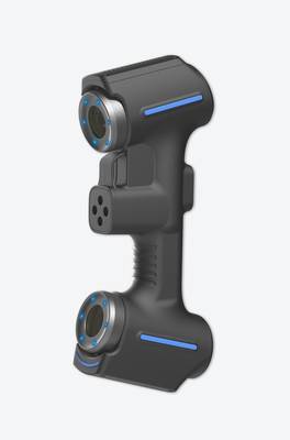
Learn how a 3D scanner to make STL files captures physical geometry and converts it into triangulated mesh data for CAD and CAM workflows.
Definition of 3D Scanners for STL File Generation
A 3D scanner built for STL file generation serves one core function: capturing physical surface geometry and converting it into a triangulated mesh dataset. The STL (stereolithography) format represents object surfaces as a collection of triangular facets. Each triangle is defined by three vertices and a surface normal. There is no color data, no texture, no parametric history. Just raw geometry.
This simplicity is why STL remains the de facto interchange format across Western manufacturing sectors.
Common Questions
What should teams check when evaluating Definition of 3D Scanners for STL File Generation?
A 3D scanner built for STL file generation serves one core function: capturing physical surface geometry and converting it into a triangulated mesh dataset.
What should teams check when evaluating Working Principles Behind 3D Scanners That Generate STL Files?
A 3D scanner to make STL files does not capture a finished CAD model in one step.
What should teams check when evaluating End-to-End Workflow?
The conversion process follows a defined sequence:
The value proposition is straightforward. Physical objects rarely exist with complete CAD documentation. Legacy tooling, worn components, hand-finished prototypes — these exist only as metal or polymer. A 3D scanner bridges that gap. It measures point coordinates across a surface, reconstructs the topology, and exports an STL that can be imported into any major CAD, CAM, or inspection software package.
| Sector | Primary STL Use Case | Typical Workflow Integration |
|---|---|---|
| Automotive OEM | Reverse engineering legacy tooling, die verification | Scan-to-CAD for replacement part design |
| Aerospace MRO | Damage assessment, wear quantification on turbine components | Scan data compared against nominal CAD for repair scope definition |
| Medical Device | Patient-specific implant geometry capture | STL exported directly to additive manufacturing or CNC milling |
| Energy Component | First-article inspection of castings, forgings | Dimensional deviation mapping against GD&T callouts |
STL output matters because it is universally readable. A quality engineer in an automotive plant can share scan data with a supplier using different CAD software without compatibility friction. The format strips away proprietary layers and leaves only geometry that can be measured, modified, or manufactured.
However, STL has inherent limitations. The mesh is a discrete approximation of a continuous surface. Scan resolution determines facet density, which affects how accurately curved surfaces are represented. Coarse scans produce faceted artifacts on radii and freeform surfaces. Fine scans produce large file sizes that strain downstream processing. Engineers must balance capture resolution against practical file management.
For industrial applications, INSVISION scanners output STL alongside other formats such as PLY and TXT. The STL export serves as the common denominator for downstream reverse engineering, inspection reporting, and additive manufacturing preparation. The scanner itself does not interpret the geometry — it measures and records.
The STL file becomes the neutral carrier of that measured reality into whatever software environment the engineering team uses next.
Working Principles Behind 3D Scanners That Generate STL Files
A 3D scanner to make STL files does not capture a finished CAD model in one step. It captures surface geometry as raw measurement data, which must pass through several processing stages before the file is usable in downstream applications. Misunderstanding these stages is a common source of quality problems in reverse engineering and inspection workflows.
End-to-End Workflow
The conversion process follows a defined sequence:
| Stage | What Happens | Impact on Final STL Quality |
|---|---|---|
| Surface data capture | Sensor records discrete points on the object surface | Determines raw resolution and noise floor |
| Point cloud generation | Multiple scans aligned into a unified coordinate set | Alignment errors compound into dimensional drift |
| Point cloud cleaning | Outliers, background artifacts, and duplicate points removed | Reduces surface noise and false geometry |
| Polygon mesh reconstruction | Points connected into triangular facets | Defines surface continuity and watertightness |
| STL export optimization | Mesh decimated, repaired, and oriented for target use | Determines file size and downstream compatibility |
Capture Technologies
Industrial scanners fall into two primary categories. Structured light systems project fringe patterns onto a surface and use camera triangulation to calculate depth. Laser-based systems sweep a line or point across the object while tracking the reflected signal. Structured light typically delivers higher point density on stationary objects; laser scanning handles darker or more reflective materials with less preparation.
Both approaches produce point clouds that serve as the foundation for mesh generation.
Why Each Stage Matters
Point cloud cleaning is where many STL files fail. Unfiltered scan data includes stray points from fixture surfaces, edge artifacts, and duplicate data from overlapping passes. These defects translate directly into mesh errors — non-manifold edges, holes, inverted normals — that downstream CAM or FEA software rejects.
During mesh reconstruction, the software connects neighboring points into triangles. The density of the source point cloud determines whether fine features survive this conversion. A radius, fillet, or sharp corner scanned at low density will appear faceted or smoothed in the final STL, regardless of how precise the individual points were.
STL export optimization involves decimation — reducing triangle count while preserving dimensional accuracy. Exporting a raw mesh without decimation produces files too large for practical use in many CNC and simulation packages. Over-decimation removes legitimate surface detail. The correct balance depends on the application: first-article inspection requires tighter tolerance preservation than concept visualization.
Dimensional Accuracy Considerations
Alignment with ISO 10360 provides a reference framework for verifying scanner performance. This standard defines acceptance tests for coordinate measuring systems, including probing error and length measurement error.
Industrial buyers evaluating a 3D scanner to make STL files for inspection or reverse engineering should request accuracy specifications that reference this standard rather than marketing figures without a defined test methodology.
INSVISION scanners document accuracy specifications against this framework, with output available in STL, PLY, and other standard formats. The final STL quality depends less on the scanner brand and more on how well each workflow stage is executed.
Key Technical Parameters for Evaluating 3D Scanners for STL Output
Selecting a 3D scanner for STL file production requires more than a glance at a spec sheet. The final STL mesh is only as useful as the measurement data behind it. A scanner that produces visually smooth geometry but cannot hold a positional tolerance will fail downstream in CAD comparison or CNC programming.
Industrial buyers need to separate marketing specifications from parameters that actually affect dimensional integrity and workflow throughput.
The table below standardizes five core parameters used across Western manufacturing environments—from automotive OEM first-article inspection to aerospace MRO and medical device reverse engineering.
| Technical Parameter | Definition | Industrial Relevance for STL Output |
|---|---|---|
| Scanning Accuracy | The maximum deviation between measured dimensions and the true physical dimensions of an object | Determines if STL files meet tight tolerance requirements for aerospace, medical, and high-precision automotive applications |
| Scanning Area | The maximum surface area a scanner can capture in a single pass | Impacts workflow speed for large components such as energy turbine housings or automotive body panels |
| Depth of Field | The range of distances from the scanner where accurate surface data can be captured | Supports efficient scanning of objects with varying surface heights or complex geometric features |
| Output Format Compatibility | The range of 3D file formats a scanner can export natively | Ensures STL files integrate seamlessly with existing industrial CAD, inspection, and additive manufacturing software stacks |
| Environmental Operating Tolerance | The range of temperature, humidity, and ambient conditions where a scanner maintains its rated performance | Enables reliable STL file production on factory floors, in MRO hangars, and other non-lab industrial environments |
Accuracy is the first gate. If a scanner cannot demonstrate repeatable deviation within the GD&T callouts on your part drawing, the resulting STL will compound errors in every downstream process. Scanning area and depth of field govern how many setups are needed to capture a part fully.
Each additional setup introduces alignment error, so a larger field of view with adequate depth often produces a cleaner mesh than stitching multiple narrow scans.
Output format compatibility is too often treated as an afterthought. An STL file that requires repair or re-meshing before it enters inspection software adds labor and introduces opportunity for data corruption. Native, clean STL export—alongside formats like PLY or ASC for other workflows—reduces friction in the digital thread.
Environmental tolerance matters because industrial scanning rarely happens in a metrology lab. Temperature drift, vibration, and airborne particulates can shift calibration. Equipment rated for factory-floor conditions will hold its accuracy where it is actually used.
Some suppliers, including INSVISION, publish these parameters directly for industrial scanner lines. When evaluating any vendor, request documented accuracy statements tied to a known reference standard, not a single favorable scan. The STL is only a container; the measurement data inside it is what your process depends on.
Ideal Use Cases for 3D Scanners Producing STL Files
The primary value of using a 3D scanner to make STL files lies in capturing physical reality where digital data is absent, inaccurate, or degraded. STL output is a mesh representation—a collection of triangles approximating a surface—which makes it ideal for visualization, rapid prototyping, and direct-to-manufacturing workflows. It is not, however, a parametric CAD model.
Understanding this boundary defines where the technology delivers maximum industrial return.
Several high-impact scenarios justify scanning-to-STL as a first step in a digital thread or lean manufacturing initiative:
- Reverse engineering legacy automotive components. Parts manufactured before widespread CAD adoption often have no surviving design data. Scanning captures the as-built geometry, producing an STL that serves as the reference mesh for tooling, aftermarket reproduction, or fitment analysis.
- Aerospace MRO replication. Worn or damaged parts removed from service can be scanned to document current condition or to reconstruct nominal geometry for replacement. The STL file provides a measurable record before destructive testing or repair.
- Custom medical implant validation. Patient-specific anatomy or pre-operative models can be scanned and converted to STL for design verification against scan data, ensuring a proposed implant matches actual bone or tissue geometry.
- Energy turbine surface analysis. Blade airfoils and combustion components accumulate erosion, pitting, and deformation over time. Scanning produces an STL that can be compared against nominal CAD or a previous scan to quantify material loss and surface deviation.
For industrial operations, the distinction between mesh capture and parametric modeling matters. An STL from a scanner represents fixed geometry. If the task is simple replication, inspection, or archiving, the STL may be sufficient.
If the task requires design modification—changing wall thicknesses, adding mounting features, adjusting tolerances, or creating a parametric family of parts—the mesh must be brought into CAD software for surface fitting, feature extraction, or hybrid modeling. Treating the STL as a final deliverable in complex design workflows leads to rework and lost time.
| Workflow requirement | STL alone sufficient? | Recommended approach |
|---|---|---|
| Archival of as-built geometry | Yes | Direct scan-to-STL |
| First-article inspection against nominal | Yes | Compare STL mesh to CAD reference |
| 3D printing or rapid prototyping | Yes | Repair mesh, export STL |
| Dimensional documentation for MRO records | Yes | Scan and archive STL with metadata |
| Parametric redesign or tolerance modification | No | Use STL as reference in CAD; rebuild features |
| Simulation or FEA with variable geometry | No | Convert mesh to solid or surface model first |
| Creating a family of similar parts | No | Parametric CAD model required |
The same principle applies to inspection workflows. A scanner with sufficient accuracy can replace touch-probe or CMM spot-checking for surface characterization, but the output format—STL—defines what downstream analysis is possible. Deviation color maps, GD&T callout evaluation, and runout checks can all be performed on mesh data within inspection software. Full parametric modification cannot.
INSVISION scanning systems output STL among other formats, making them compatible with this workflow. The file format itself is the more important consideration for industrial buyers. When evaluating whether to use a 3D scanner to make STL files, the question is not whether the scanner can produce the format—most can—but whether the downstream process is mesh-tolerant or requires parametric geometry.
Answering that question before purchasing or deploying equipment prevents mismatched expectations and wasted scanning effort.
Common Misconceptions About 3D Scanners for STL File Creation
The STL file format remains the workhorse of industrial 3D data exchange, yet misunderstandings about how scanner-generated STL files behave in real manufacturing workflows persist. Three misconceptions surface repeatedly in engineering discussions, and each deserves technical correction.
Misconception 1: Scanner-generated STL files are ready for immediate industrial use.
A raw STL from any 3D scanner represents a point cloud converted into a triangular mesh. That conversion does not automatically produce a manufacturable surface. In practice, the mesh typically contains overlapping triangles, non-manifold edges, holes from occluded areas, and noise artifacts. Downstream CAD packages may reject or misinterpret such geometry.
Industrial users must perform mesh cleanup, hole filling, decimation, and surface reconstruction before the file is suitable for CNC programming, simulation, or metrology comparison. The scanner outputs data; it does not output design intent.
Misconception 2: Higher scan resolution always produces more useful STL files.
Resolution and utility are not linearly related. Scanning at maximum resolution on a large die-cast part may generate hundreds of millions of triangles, overwhelming CAM software and inspection routines. The triangle count must match the downstream task. GD&T comparison against a nominal CAD model often performs better with a decimated, uniformly sampled mesh than with a dense, irregular one.
A well-planned scan strategy balances point spacing against the smallest feature that must be captured. More data is not better data.
Misconception 3: STL files from 3D scanners cannot meet aerospace or medical quality standards.
This claim conflates file format with measurement integrity. STL is a surface representation format, not a quality standard. What matters is the metrological performance of the scanner itself, validated under ISO 10360 for dimensional accuracy, and the dimensional documentation practices aligned with ASME Y14.41 for digital product definition.
Scanners with certified volumetric accuracy in the sub-0.030 mm range, when operated within calibrated working volumes and with proper reference targets, produce STL meshes suitable for aerospace MRO inspection and medical device reverse engineering. The standard compliance belongs to the measurement system and process validation, not to the file extension.
The table below summarizes practical configuration tradeoffs for STL output in industrial contexts.
| STL Output Consideration | Low Resolution / Fast Scan | High Resolution / Detailed Scan | Industrial Guidance |
|---|---|---|---|
| Mesh size (triangle count) | Smaller file, faster processing | Larger file, slower processing | Match density to downstream software limits |
| Feature capture | Misses small radii, sharp edges | Captures fine features, threads, engraving | Scan only at resolution needed for the tolerance band |
| Noise sensitivity | Less sensitive to ambient vibration | More sensitive to environmental disturbance | Control temperature and vibration for tight-tolerance work |
| Inspection fit-to-CAD | Faster deviation mapping | Higher fidelity on complex freeform surfaces | Use decimated mesh for GD&T, full mesh for surface analysis |
| Storage and archival | Lightweight for ERP/PLM integration | Requires substantial data management | Plan retention per ASME Y14.41 digital dataset requirements |
INSVISION scanners output STL alongside PLY, ASC, and other formats, giving engineers flexibility in how they route scan data into inspection or reverse engineering pipelines. The practical point is not which format the scanner exports, but whether the measurement system behind that export is validated for the accuracy the application demands.
Related Industrial 3D Digitalization Concepts
A 3D scanner used to make STL files does not operate in isolation. The resulting mesh is a geometric input that feeds several established industrial workflows. Understanding how STL data interacts with these adjacent concepts clarifies where scanning adds measurable value and where downstream processing remains necessary.
Point cloud data is the raw measurement output from most optical scanners. Before an STL exists, the system captures millions of XYZ coordinates, often with intensity or color attributes. Software then converts this unstructured point set into a polygon mesh through triangulation, decimation, and hole-filling.
The STL format stores only the final triangle vertices and face normals — it discards the original point density and scan metadata. Engineers who need to audit measurement uncertainty or re-mesh at different tolerances should therefore retain native point cloud exports alongside the STL.
Reverse engineering is the most common application when physical parts lack CAD documentation. The scan-to-STL step produces a faceted reference, but parametric CAD reconstruction still requires surfacing or feature extraction work. STL files alone are insufficient for modifying design intent, adding GD&T callouts, or rebuilding a clean feature tree.
Digital twin integration uses the STL as a lightweight geometric snapshot. In automotive and aerospace MRO environments, scanned assets are aligned to nominal CAD inside metrology software, generating color deviation maps. This supports wear analysis, assembly verification, and as-built documentation without importing heavy point clouds into PLM systems.
First article inspection (FAI) under AS9102 or ISO 9001 requirements increasingly accepts scanned STL data as supplementary evidence. However, the STL must be paired with inspection reports showing measured values, tolerance bands, and datum alignment. A raw mesh is not an inspection record by itself.
Additive manufacturing preparation is where STL remains the de facto exchange format. Scanned meshes must be watertight, manifold, and correctly scaled before slicing. Print preparation software typically flags inverted normals, non-manifold edges, and self-intersections — defects that originate in the scanning and meshing stage.
| Workflow Stage | Data Format | Typical Downstream Action |
|---|---|---|
| Raw acquisition | Point cloud (PLY, ASC) | Alignment, filtering, uncertainty review |
| Mesh generation | STL, OBJ | Watertight repair, decimation, smoothing |
| Reverse engineering | STL → CAD surfaces | Feature extraction, parametric rebuild |
| Inspection | STL + nominal CAD | Deviation analysis, FAI reporting |
| Digital twin | STL (lightweight) | PLM archiving, as-built comparison |
| 3D printing | STL (watertight) | Slicing, support generation, build simulation |
Across automotive, aerospace, medical, and energy sectors, the pattern is consistent: STL files from 3D scanners are an intermediate deliverable, not the final engineering output. Organizations that define mesh quality criteria, archive point cloud data, and integrate scanning into existing QMS and PLM structures extract more value than those treating scan-to-STL as a standalone conversion task.
INSVISION scanning systems support direct STL output for these workflows, but the format choice should follow from the downstream use case — inspection, reverse engineering, or additive manufacturing — rather than defaulting to STL as the only export option.
INSVISION Industrial 3D Scanning Solutions for STL Output
STL remains the de facto exchange format for mesh-based workflows, from additive manufacturing to CFD surface preparation. A 3D scanner to make STL files must therefore produce watertight, manifold meshes with consistent triangle density — not merely export raw point clouds under an STL extension.
The distinction matters in production environments where downstream CAM, slicing, or inspection software rejects non-manifold geometry outright.
INSVISION designs its industrial scanning portfolio around this requirement. The systems natively export STL alongside other common formats, including PLY, OBJ, TXT, IGS, and ASC, with select platforms offering additional customization. This multi-format capability addresses a practical constraint in Western manufacturing: design, quality, and production teams rarely standardize on a single software ecosystem.
A scan captured for first-article inspection may need to move into a CAD environment for reverse engineering, then into a slicer for prototype output — each with distinct format expectations.
| File Format | Typical Industrial Use | INSVISION Native Support |
|---|---|---|
| STL | Additive manufacturing, rapid prototyping, mesh inspection | Yes |
| PLY | Color/attribute-rich point and mesh data | Yes |
| OBJ | CAD interchange with texture references | Select systems |
| IGS | NURBS/surface transfer to parametric CAD | Select systems |
| ASC | Raw coordinate export for custom analysis | Yes |
The engineering priority is repeatability. In quality inspection contexts, scan data must align with GD&T callouts and tolerance bands without post-processing drift. In reverse engineering, mesh quality directly influences the accuracy of surface reconstruction.
INSVISION’s systems are built for these industrial demands — high-accuracy scanning for dimensional verification, and large-format capture for components where manual measurement is impractical or error-prone.
Format flexibility does not substitute for metrological integrity, but it determines how cleanly scan data integrates into existing workflows. For procurement teams evaluating scanning infrastructure, the relevant criterion is not whether a device exports STL — most do — but whether the generated STL files hold up under inspection software and CAM toolpaths without rework.
That is the practical standard INSVISION’s industrial portfolio is engineered to meet.
Frequently Asked Questions About 3D Scanners for STL Files
Can STL files from industrial 3D scanners be used directly for metal additive manufacturing?
Not usually without intermediate processing. STL output from most structured-light or laser scanners is a dense mesh representing the as-built or as-is surface. Metal AM build preparation software typically expects a closed, watertight mesh with limited triangle counts and specified tolerances. Scanned meshes often contain holes, overlapping triangles, or excessive file size.
Plan for a repair step—decimation, hole filling, and normal alignment—inside software such as Materialise Magics or Netfabb before slicing.
How do I verify dimensional accuracy of a scanner-generated STL?
Use a calibrated reference artifact. Scan a traceable sphere or gauge block, then compare the mesh deviation against known dimensions in inspection software. For industrial work, align to GD&T callouts and check form errors such as flatness or runout against the scanner’s published accuracy specification. Acceptable deviation depends on your tolerance band;
a scanner rated at ±0.020 mm is not automatically sufficient for ±0.050 mm features if environmental or surface conditions introduce additional error.
What other file formats are typically offered alongside STL?
Most industrial scanners export PLY and TXT as standard. Some offer OBJ, IGS, or ASC. The table below summarizes common formats by purpose.
| Format | Typical Use | Notes |
|---|---|---|
| STL | AM, rapid prototyping | Mesh only, no color or units |
| PLY | Color scans, inspection | Supports vertex color |
| OBJ | CAD exchange, rendering | Mesh plus texture references |
| IGS/IGES | CAD surface modeling | Requires NURBS conversion |
How do factory floor environmental conditions affect STL file quality?
Ambient vibration, temperature drift, and airborne particulates degrade scan data. Structured-light scanners are sensitive to ambient infrared or bright sunlight. Dust or coolant mist on the part surface creates noise that appears as mesh roughness in the STL. Industrial scanners with IP54-rated housings tolerate some contamination, but the scan quality still depends on a stable thermal environment and clean, matte surfaces.
For repeatable results, fixture the part, allow thermal soak, and avoid scanning near active machining centers.
Can STL files from 3D scanners be imported into mainstream industrial CAD software?
Yes, but with limitations. SolidWorks, Inventor, and Siemens NX import STL as mesh bodies, not as editable solid geometry. You cannot directly modify features or apply parametric dimensions. Reverse-engineering workflows require surface fitting or NURBS conversion—often a semi-automated process using tools like Geomagic Design X or native CAD surfacing functions.
If your downstream need is inspection only, import the STL into polygonal inspection software and compare against the nominal CAD model using best-fit alignment. INSVISION systems support STL and PLY export as standard, with additional formats available depending on the application.
Key Takeaways for Industrial Users
Industrial adoption of a 3D scanner to make STL files starts with understanding what the tool actually does. The scanner captures surface geometry as point-cloud data. Software then converts that data into a triangular mesh — the STL file — which downstream systems can read for reverse engineering, inspection, or additive manufacturing. The STL itself contains no color, material, or tolerance metadata.
It is a geometric representation only.
What matters in practice is whether the scanner can hold the tolerances your workflow requires. Evaluation parameters break down into a few practical categories.
| Parameter | What It Tells You |
|---|---|
| Volumetric accuracy | Deviation across the full measurement volume, not just at a single point |
| Resolution | Smallest feature the scanner can resolve on the surface |
| Depth of field | Working distance range that maintains usable data quality |
| Output format flexibility | Whether the scanner exports STL, PLY, or native formats without extra conversion steps |
| Environmental tolerance | How reliably the scanner performs under shop-floor lighting, temperature, and vibration |
The right use case defines the right scanner. A handheld unit works for large castings and weldments where access matters more than sub-20-micron accuracy. A structured-light or tracked system suits first-article inspection of machined components with tight GD&T callouts. Matching the tool to the tolerance band is the core decision. Buying more accuracy than needed adds cost and slows workflows.
Buying less produces STL files that look clean but fail inspection downstream.
For Western manufacturers, this connects directly to Industry 4.0 initiatives. A reliable 3D scanner to make STL files feeds digital twin workflows, closes the loop between as-built and as-designed geometry, and reduces rework cycles in automotive OEM, aerospace MRO, and medical device production. The scanner is not a standalone purchase — it is an input to a broader digital manufacturing pipeline.
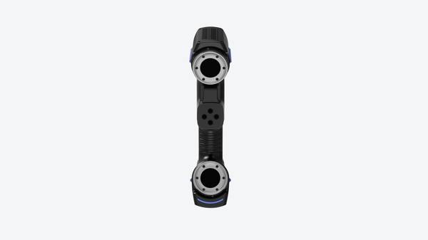
INSVISION provides industrial-grade 3D scanning solutions that support reliable STL file generation for global manufacturing sectors.
- What Is 3D Scanning? Principles, Workflow, and Industrial Applications 3D scanning is a digital measurement technology that converts the surface geometry of physical objects into 3D data. This entry covers its working principles, core parameters, industrial use cases, common misconceptions, and related technical…
- What Is a 3D Scanner? Types, Parameters, and Selection Criteria A 3D scanner captures three-dimensional surface data from physical objects and converts geometry, dimensions, and features into digital data for inspection, reverse engineering, and modeling.
- What Is 3D Scanning Accuracy? Accuracy, Repeatability, and Resolution Explained 3D scanning accuracy describes how closely scan data matches an object's actual geometry and dimensions. It is assessed through local accuracy, volumetric accuracy, stitching accuracy, repeatability, and resolution.
- What Is Point Cloud Data? Point Clouds, Meshes, and CAD Models in 3D Scanning Point cloud data is an important raw data format in 3D scanning. It consists of discrete 3D coordinate points that describe object surface geometry and support inspection, reverse engineering, modeling, and archiving.
Hangzhou Insvision Technology Co., Ltd.
Address: Building 1, No. 1399 Liangmu Road, Yuhang District, Hangzhou, Zhejiang 311121, China
Copyright © Hangzhou Insvision Technology Co., Ltd. All rights reserved.
Copyright © Hangzhou Insvision Technology Co., Ltd. All rights reserved.