

3D scanner for cars: Principles, Evaluation Criteria, and Practical Boundaries
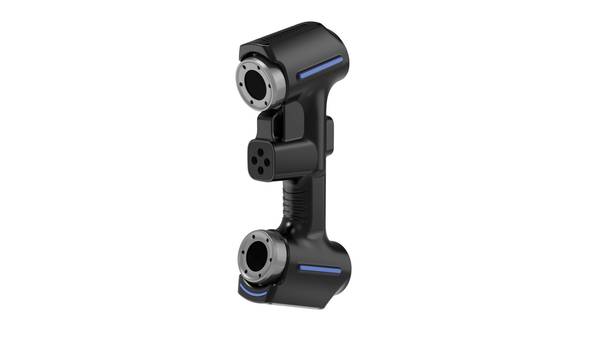
3D scanner for cars: a guide to acquisition principles, evaluation criteria, processing steps, method limits, equipment checks, and acceptance boundaries.
Definition and Scope
A 3D scanner for cars is any optical measurement device that captures surface geometry from a vehicle, subassembly, or individual component and converts it into point-cloud or mesh data. The term covers handheld structured-light units, arm-mounted laser heads, and stationary photogrammetry rigs. Scope depends on the deliverable, not the hardware class.
The same scan dataset can serve four distinct workflows, and treating them as interchangeable creates specification errors.
| Deliverable | Primary output | Typical downstream use |
|---|---|---|
| Capture | Raw point cloud or mesh | Archival, reverse engineering, digital twin baseline |
| Inspection | Deviation map against CAD or GD&T callouts | First-article checks, weld distortion review, flush-and-gap validation |
| Modeling | Watertight NURBS or parametric surface | Tooling design, aftermarket part development, simulation prep |
| Approval | Signed dimensional report | PPAP-style documentation, supplier acceptance, engineering sign-off |
Capture emphasizes coverage and resolution.
Data-Capture Principles
Before relying on a 3D scanner for cars, confirm that the surface is optically visible to the sensor and that the scanner’s projection pattern can return a stable signal from the material. If the panel is glossy, transparent, or heavily oiled, the capture path changes; a matte developer or adjusted exposure may be required before any coordinate data is meaningful.
Optical capture converts reflected light into surface points, but only where visibility and surface response overlap. Those points then resolve into a coordinate formation tied to a reference frame, producing measurable geometry rather than a photograph.
| Principle | What It Determines |
|---|---|
| Optical capture | Whether the sensor receives usable light from the surface |
| Visibility | Which areas can be measured without occlusion or reflection loss |
| Surface response | How the material returns light to the sensor |
| Coordinate formation | How individual points become a dimensional dataset |
Key Evaluation Criteria
Evaluation should connect each criterion to evidence and a verification method, while unresolved items remain open.
| Criterion | Meaning | Required evidence | Verification method |
|---|---|---|---|
| Target coverage | Whether planned surfaces and features enter the data | Task definition and region list | Check covered and uncovered areas on a representative part |
| Data usability | Whether the output enters the downstream inspection or modeling workflow | File and interface requirements | Import and read back the output in the target workflow |
| Acceptance traceability | Whether the decision maps to a criterion, version, and reviewer | Approval and change records | Retain settings, evidence, and unresolved items |
Data-Processing Workflow
The data-processing workflow should keep capture, cleanup, alignment, meshing, comparison, and export as separately recorded stages. Each stage needs a defined input, output, and verification boundary before data moves forward.
| Stage | Primary output | Verification boundary |
|---|---|---|
| Capture | Raw point or range data | Record target coverage, missing regions, and capture conditions |
| Cleanup | Data with unrelated points removed | Confirm that required edges, holes, and datum features remain |
| Alignment | Data in one coordinate system | Record the reference method, selected datums, and residual result |
| Meshing | Surface data for downstream use | Review the scope of hole filling, smoothing, and simplification |
| Comparison | Deviation results against nominal data | Bind the reference version, tolerance band, and evaluated region |
| Export | Target file or report | Import and read back units, coordinates, and required entities downstream |
Use Boundaries and Limitations
A verification boundary exists wherever a surface cannot be seen directly by the sensor. Occlusion behind brackets, inside deep channels, or under flanges forces the scan path to change, and reflective paint or bare machined metal can return unreliable data unless the surface is prepared or the exposure is adjusted.
Fine detail such as small fastener holes or engraved characters requires a tighter scan pitch, while larger body panels tolerate wider spacing.
Datum strategy matters before scanning begins.
| Condition | Primary effect | Verification response |
|---|---|---|
| Occlusion | Missing geometry behind features | Add scan positions or rotate part |
| Reflective surface | Noise, holes, or false peaks | Matte developer or exposure control |
| Fine detail | Rounded edges, lost small features | Reduce scan pitch and standoff |
| Weak datum plan | Stable fit but wrong deviation origin | Lock targets to GD&T datum features |
Common Misconceptions
One verification boundary is overlooked: a scan file that opens without error is not the same as a scan file that has been accepted against the part’s dimensional requirements. Nominal specifications describe the design intent. Scan completion describes data capture. Neither condition proves that the captured geometry falls within the tolerance zones called out on the drawing.
A 3D scanner for cars can produce a dense mesh quickly, but mesh density does not validate a GD&T callout. A surface may appear smooth on screen while still exceeding a profile tolerance or missing a hole position.
| Condition | What it confirms | What it does not confirm |
|---|---|---|
| Scan completed | Data capture finished | Feature conformance |
| Nominal specification listed | Design intent defined | Measured deviation within tolerance |
| Mesh visually complete | Surface coverage | Runout, position, or profile acceptance |
Related Concepts
Related concepts need separate deliverables and decision boundaries; one capture does not by itself complete every downstream task.
| Concept | Typical output | Decision boundary |
|---|---|---|
| 3D scanning | Point or range data | Confirm target coverage and capture conditions |
| 3D digitization | Storable and exchangeable geometry | Confirm completeness, coordinates, and format |
| Dimensional inspection | Evaluation against a reference or tolerance | Confirm datums, versions, and acceptance rules |
| Reverse engineering | Geometry used for reconstruction | Confirm coverage and downstream modeling requirements |
| CAD reconstruction | Parametric or surface model | Confirm intended use, interfaces, and review requirements |
Whether one captured data set can support several tasks must be verified against each task’s output and acceptance evidence.
Equipment and Supplier Validation
Equipment and supplier validation should use a representative part that covers the target geometry, surface condition, visibility, and datum requirements. Check whether the target area is captured, whether the point cloud or mesh can be exported in the required format, and whether the downstream system can read it.
Keep capture settings, missing regions, reference method, interface result, and acceptance evidence in the same validation record.
Reviewed official product documentation places AlphaScan handheld 3D scanner within the application scope discussed here. That source establishes only the product and use boundary stated by the publisher; it does not establish fitness for every part. A final decision still requires representative-part capture, interface readback, and predefined acceptance criteria.
Frequently Asked Questions
What must be defined before data capture begins?
Define the required data, inspection decision, model file, or approval result, with separate inputs, outputs, and acceptance evidence. Captured scan data does not by itself complete inspection, modeling, or approval.
How should a representative part be validated?
Choose a part that covers the target geometry, surface response, visibility, and datum conditions, then document capture settings, alignment, and output format. Judge suitability against the approved task criteria, not merely against scan completion.
What can official documentation establish?
Official documentation supports only the specifications, interfaces, and product scope that it states. Suitability for a particular part, environment, workflow, and acceptance rule still requires representative-part validation.
- What Is 3D Scanning? Principles, Workflow, and Industrial Applications 3D scanning is a digital measurement technology that converts the surface geometry of physical objects into 3D data. This entry covers its working principles, core parameters, industrial use cases, common misconceptions, and related technical…
- What Is a 3D Scanner? Types, Parameters, and Selection Criteria A 3D scanner captures three-dimensional surface data from physical objects and converts geometry, dimensions, and features into digital data for inspection, reverse engineering, and modeling.
- What Is 3D Scanning Accuracy? Accuracy, Repeatability, and Resolution Explained 3D scanning accuracy describes how closely scan data matches an object's actual geometry and dimensions. It is assessed through local accuracy, volumetric accuracy, stitching accuracy, repeatability, and resolution.
- What Is Point Cloud Data? Point Clouds, Meshes, and CAD Models in 3D Scanning Point cloud data is an important raw data format in 3D scanning. It consists of discrete 3D coordinate points that describe object surface geometry and support inspection, reverse engineering, modeling, and archiving.
Hangzhou Insvision Technology Co., Ltd.
Address: Building 1, No. 1399 Liangmu Road, Yuhang District, Hangzhou, Zhejiang 311121, China
Copyright © Hangzhou Insvision Technology Co., Ltd. All rights reserved.
Copyright © Hangzhou Insvision Technology Co., Ltd. All rights reserved.