

3D Scanner for Big Objects Core Concepts and Technical Criteria
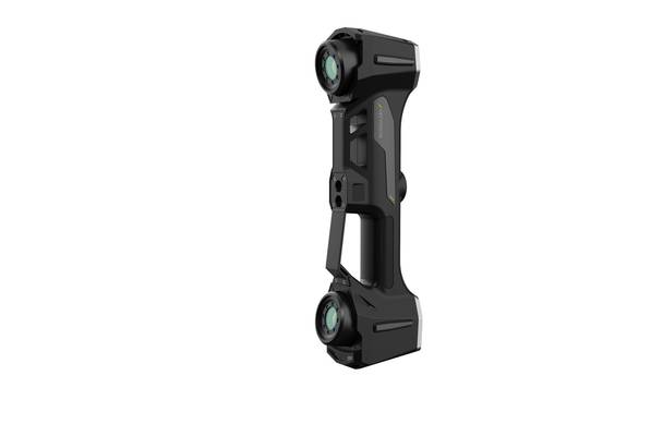
3d scanner for big objects: Definition of 3D Scanners for Big Objects Definition of 3D Scanners for Big Objects A 3D scanner for big objects is a non-contact.
Definition of 3D Scanners for Big Objects
Definition of 3D Scanners for Big Objects
A 3D scanner for big objects is a non-contact dimensional measurement system engineered to capture full-field surface geometry from parts whose characteristic dimensions exceed the practical single-setup range of conventional small-format scanners. In industrial practice, “big objects” typically means workpieces spanning roughly one meter to several meters in any axis.
Common examples include automotive body-in-white assemblies, aerospace fuselage sections and wing skins, wind turbine blade root sections, heavy equipment castings, and large injection-molded or thermoformed panels.
Key Points at a Glance
- A 3D scanner for big objects is a non-contact dimensional measurement system engineered to capture full-field surface geometry from parts whose…
- Large-format 3D scanning addresses a fundamental metrology problem: how to capture dimensional data from objects that exceed the measurement vol…
- Large-format scanning fails fast when evaluation criteria are vague.
- Application boundaries for large-format 3D scanning are not defined by part volume alone.
The core functional purpose of these systems is not simply to scan a large surface, but to do so while minimizing segmentation errors. Smaller scanners require multiple setups and alignment targets to cover a large part. Each registration step introduces cumulative error.
A large-format scanner, by contrast, captures a wider measurement band per pass and uses an external tracking device or wide-area reference network to maintain a common coordinate frame across the entire part. This yields a single, coherent point cloud or mesh with controlled volumetric accuracy.
In metrology terms, large-format scanning addresses a specific problem: holding tight dimensional tolerances over long distances. A scanner with a small field of view may deliver excellent local accuracy but poor global continuity across a 2-meter casting. A large-object scanner is designed so that the global coordinate system remains stable even when the operator moves around the part.
This matters for first-article inspection, tooling verification, and MRO workflows where the entire part must be evaluated against CAD or GD&T callouts as one dataset.
For industrial buyers, the distinction is practical. If the part requires multiple setups, stitching software, and reference targets just to capture one surface, the measurement workflow becomes slow and error-prone. A large-format system reduces that burden. The table below outlines typical dimensional boundaries and application classes.
| Application Class | Typical Part Size Range | Primary Metrology Challenge |
|---|---|---|
| Automotive body-in-white | 1.5–5 m | Global surface continuity, hole position accuracy |
| Aerospace fuselage sections | 3–8 m diameter | Curvature verification, fastener pattern inspection |
| Wind turbine blade sections | 2–10 m along chord | Airfoil profile tolerance, leading-edge smoothness |
| Heavy equipment castings | 1–4 m | Core shift detection, stock allowance mapping |
| Large composite panels | 1–6 m | Spring-back analysis, trim line verification |
INSVISION positions its large-format scanning technology within this scope, though the definition above applies to the category as a whole. The key evaluation criterion for any such system is whether it can capture the full part in a single stable coordinate frame with acceptable volumetric accuracy. That capability, more than raw scan speed or point density, defines whether a scanner is genuinely suited to big objects.
Working Principles of Large-Format 3D Scanning Systems
Large-format 3D scanning addresses a fundamental metrology problem: how to capture dimensional data from objects that exceed the measurement volume of a single sensor. A handheld scanner might cover 500 mm in one pass. A wind turbine blade, aircraft fuselage section, or injection mold can span several meters. No single optical frame can resolve that volume while maintaining tight tolerance.
The solution is architectural, not optical. Large-format systems combine a local scanning device with a wide-area tracking mechanism. The scanner captures dense point data from the surface. The tracker establishes a global coordinate frame. As the operator moves the scanner across the object, the tracker continuously records its position and orientation.
This pairing allows the system to assemble thousands of individual captures into a single, coherent dataset without losing spatial reference.
Reference target alignment offers an alternative approach. Instead of active tracking, the system uses adhesive or magnetic reference markers placed on or around the object. Each scan frame must contain a minimum number of visible targets. The software identifies these targets across overlapping frames and computes the rigid transformation between them.
This method works well for objects that remain stationary during scanning and where marker placement does not interfere with surface data collection. The trade-off is setup time. Marker placement on a large forging or composite layup can take as long as the scanning itself.
Structured light and laser triangulation represent the two dominant data capture methodologies. Structured light systems project a known pattern — typically sinusoidal fringes or binary codes — onto the surface. One or more cameras observe the pattern deformation and reconstruct 3D coordinates through triangulation. These systems deliver high point density and excellent noise characteristics on matte, cooperative surfaces.
Laser-based systems project a line or cross pattern and track its profile across the surface. They tolerate ambient light better and handle reflective or dark surfaces more reliably, which matters in foundry and fabrication environments.
| Method | Typical Strengths | Common Limitations |
|---|---|---|
| Structured light | High point density, low noise on matte surfaces | Sensitive to ambient light, struggles with reflective parts |
| Laser triangulation | Better on dark or shiny surfaces, works in brighter environments | Lower point density per pass, slower on large flat regions |
| Tracker-based alignment | No target placement required, operator can move freely | Requires line of sight between scanner and tracker |
| Reference target alignment | Works without active tracking hardware | Marker setup time, targets may obscure surface areas |
Maintaining accuracy across expansive volumes depends on how the system handles error accumulation. Every scan-to-scan alignment introduces a small residual error. When thousands of frames are stitched together, those residuals can compound. Fixed reference points serve as anchor constraints. The software recognizes the same reference features across multiple captures and uses them to constrain the global optimization.
This bundle adjustment process distributes alignment error across the entire dataset rather than allowing it to propagate linearly from the first scan to the last.
Integrated tracking hardware offers a different error profile. Because the tracker observes the scanner position in real time, each frame is referenced to a stable external coordinate system rather than to the previous frame. This breaks the error accumulation chain. The scanner can be removed from the object, repositioned, and brought back without losing registration.
For objects that cannot be moved or rotated — large tooling fixtures, in-situ machinery — this capability is essential.
Industrial applications impose additional requirements beyond raw geometry capture. Quality managers typically need surface deviation reports against CAD models. Engineers working with GD&T callouts expect feature-based measurements, not just point clouds. The data pipeline from large-format scanning must therefore support mesh generation, CAD comparison, and export to inspection software.
Western manufacturing environments increasingly tie these workflows into broader Industry 4.0 infrastructure, where scan data feeds digital twin models and statistical process control systems.
INSVISION has developed large-format scanning solutions that incorporate tracker-based architectures and structured light methodologies. Their approach emphasizes tight integration between scanning hardware and post-processing software, though the core working principles described here apply across the industry.
For engineering teams evaluating large-object scanning, the critical assessment criteria remain consistent: tracking architecture, surface compatibility, error accumulation behavior, and software interoperability with existing inspection workflows.
Key Performance Criteria for Evaluating 3D Scanners for Big Objects
Large-format scanning fails fast when evaluation criteria are vague. Buyers comparing systems for automotive tooling, aerospace MRO, or energy castings need to separate marketing spec sheets from parameters that hold up on a shop floor. Five non-negotiable criteria govern whether a 3D scanner for big objects can actually handle large parts without excessive stitching, drift, or data loss.
| Performance Criterion | Technical Definition | Industrial Relevance for Large Parts |
|---|---|---|
| Measurement accuracy | Maximum deviation between scanned point data and true geometry, typically expressed in microns. | Large parts amplify error accumulation. Tight tolerances on mating surfaces or GD&T callouts require scanner accuracy that does not scale with part size. |
| Single-capture scanning area | The physical area covered per scan frame without moving the scanner. | Larger frames reduce scan count and alignment error. Fewer registrations mean less cumulative deviation across a 2-meter or 5-meter workpiece. |
| Depth of field | The distance range over which the scanner maintains usable focus and accuracy. | Deep depth of field tolerates surface curvature and uneven fixtures. Operators spend less time repositioning around deep pockets or tall flanges. |
| Supported data formats | Native output types such as STL, PLY, IGES, STP, or DXF/DWG. | Direct compatibility with CAM and inspection software avoids time-consuming mesh conversion or rework in CATIA CPD or FiberSIM workflows. |
| Industrial system integration capability | Ability to connect with MES, third-party databases, or automated scanning cells. | Large-part inspection often sits inside an automated line. The scanner must export data or trigger events without manual file handling. |
Each criterion affects throughput, not just image quality. A scanner with high accuracy but a small capture area becomes impractical for a 2.5-meter stamping die. A large area but shallow depth of field forces constant refocusing. Integration capability matters when first-article inspection feeds directly into a digital twin or MES record.
INSVISION systems, for example, document scanner accuracy up to 0.020 mm and tracker accuracy up to 0.025 mm, with scanning areas reaching 1100 mm × 800 mm per frame. Those values set a useful reference point, but the evaluation should always tie the number to the specific part family being scanned.
Valid Application Boundaries for Large-Format 3D Scanning
Application boundaries for large-format 3D scanning are not defined by part volume alone. A component can be physically enormous yet geometrically simple, requiring far less measurement density than a smaller part with tight GD&T callouts. The valid boundary is instead determined by three interacting variables: required accuracy, surface geometry complexity, and environmental stability during data capture.
Parts with freeform surfaces, deep recesses, or sudden section changes demand scanners with wider depth of field and higher point density. Parts with large flat planes and modest tolerances can be validated with sparser data.
Standards alignment matters here. ISO 10360 defines acceptance testing for coordinate measuring systems, establishing how volumetric accuracy is verified against reference artifacts. ASME Y14.5 governs how dimensional tolerances and datum references are interpreted from the resulting point cloud. A scanning workflow that cannot demonstrate traceability to these frameworks has no valid application in Western manufacturing.
The boundary is crossed when the scanner’s measurement uncertainty—under actual shop-floor conditions—exceeds a defined fraction of the part’s tolerance band.
Environmental conditions frequently determine whether an application is valid before accuracy specifications do. Thermal expansion in large steel or aluminum structures can shift dimensions by hundredths of a millimeter within minutes. Vibration from nearby machining, overhead cranes, or vehicle traffic introduces noise that no software filter can fully remove without distorting true surface features.
Valid applications require either controlled environments or compensation strategies such as scale bars, reference targets, or photogrammetry-assisted alignment.
Application boundaries by sector
| Sector | Valid large-format applications | Boundary-limiting factors |
|---|---|---|
| Automotive OEM | Tooling verification, body-in-white dimensional inspection | Part temperature stability, fixture rigidity, GD&T tolerance stack-up |
| Aerospace MRO | Fuselage section alignment, composite repair assessment | Hangar temperature drift, surface finish variation, access to hidden datums |
| Energy | Wind turbine blade geometry mapping, hydroelectric component inspection | Outdoor wind loading, blade flexure during scanning, surface contamination |
| Heavy manufacturing | Large casting and forging validation | Rough as-cast surfaces, datum establishment on unmachined features, thermal mass |
The table shows that each sector reaches its boundary for different reasons. Automotive body-in-white inspection is bounded by the need to correlate scan data with the original datum scheme established in the assembly fixture. Aerospace MRO work is bounded by access: if a scanner cannot physically reach a datum feature inside a fuselage section, the alignment becomes unverifiable.
Wind turbine blade mapping is bounded by the structure’s own movement; a blade deflects under its own weight differently depending on orientation.
Misconceptions about size persist. A scanner with a large field of view does not automatically produce valid results on a large part. Field of view affects acquisition speed and data density, not measurement accuracy. Similarly, a tracker with an extended working range does not eliminate the need for stable reference geometry.
The valid boundary is crossed when the operator can no longer demonstrate, with documented evidence, that the measurement uncertainty falls within the tolerance budget defined by the drawing.
For parts approaching the upper limit of practical scanning, hybrid approaches become necessary. Photogrammetry establishes a global reference network of coded targets, verified against calibrated scale bars. The scanner then captures local regions, and each region is transformed into the global coordinate system. This works only when the target network remains stable for the duration of the capture.
Large castings and forgings present a different challenge: datum features are often unmachined, making it difficult to establish a repeatable alignment that matches how the part will be fixtured during machining. The application boundary here is defined by datum accessibility, not scanner range.
INSVISION equipment supports large-format applications where the workflow respects these boundaries. The relevant specifications—accuracy, depth of field, scanning area—must be evaluated against the specific tolerance requirements and environmental conditions of each application.
No scanner specification can substitute for a properly defined measurement plan that accounts for thermal effects, datum strategy, and verification against known reference standards.
Common Misconceptions About 3D Scanning for Big Objects
Procurement teams and engineering departments often dismiss large-format 3D scanning based on assumptions that were true a decade ago. Those assumptions now lead to unnecessary capital expenditure or continued reliance on slow, manual measurement methods. The most persistent misconceptions fall into three categories: accuracy tradeoffs, part logistics, and surface compatibility.
Misconception 1: Larger scanning volumes always reduce accuracy. This is the most damaging myth. Engineers assume that a scanner covering a \(1100\text{ mm} \times 800\text{ mm}\) area must sacrifice resolution or dimensional precision compared to a small desktop unit. Modern structured-light and laser tracking systems separate the roles of photogrammetric positioning from surface detail capture.
A tracker can maintain volumetric accuracy across a \(2600\text{ mm} \times 2200\text{ mm}\) working zone while the scanner itself holds accuracy to \(0.020\text{ mm}\). The key variable is not scan area but the stability of the reference frame. When a tracker maintains a fixed relationship to the part, the scanner’s single-frame accuracy propagates across the entire surface without drift accumulation.
The table below clarifies the relevant parameters.
| Parameter | Scanner (typical large-format) | Tracker / Positioning System |
|---|---|---|
| Accuracy | Up to \(0.020\text{ mm}\) | Up to \(0.025\text{ mm}\) |
| Depth of Field | \(650\text{ mm}\) | \(2300\text{ mm}\) |
| Scanning Area | \(1100\text{ mm} \times 800\text{ mm}\) | \(2600\text{ mm} \times 2200\text{ mm}\) |
Misconception 2: Big objects must be disassembled or moved to a lab. This assumption stems from older CMM workflows where the part had to fit within a machine’s envelope. A portable scanner with a wide tracking volume can be set up directly on the shop floor, beside a die, a weldment, or an aircraft wing fixture. The scanner moves around the stationary part; the part does not move to the scanner.
This eliminates rigging costs, transportation risk, and the downtime associated with teardown. It also allows in-process inspection of assemblies that cannot be disassembled without destroying the alignment state.
Misconception 3: Reflective or composite surfaces scan poorly on all systems. Large parts in aerospace and automotive often have machined aluminum surfaces, carbon fiber, or gloss paint. Untreated, these surfaces do create scan noise. However, the issue is optical, not fundamental. The correction is a combination of scanner exposure control and, more commonly, a light matting spray applied to the surface.
For very large parts, full-surface spraying is impractical. Here, hybrid approaches work: spray only the critical GD&T features and use the natural surface data elsewhere for reference geometry. Some scanners also handle high dynamic range scenes better than older single-exposure systems. The engineering decision is not whether to scan, but where to apply surface preparation.
INSVISION’s large-format scanning approach separates the tracker’s volumetric reference from the scanner’s high-resolution capture, making these misconceptions obsolete. The practical result is that first-article inspection, assembly verification, and reverse engineering of large tooling can happen at the point of manufacture, without moving the part or accepting lower accuracy.
Related Industrial Metrology and Manufacturing Concepts
Large-format 3D scanning intersects with several established manufacturing frameworks. The connection is practical, not theoretical—each framework depends on accurate dimensional data from physical assets.
GD&T compliance for large assemblies. Fixed CMMs struggle with parts exceeding their measurement envelope. A 3D scanner for big objects captures full-surface geometry without the staging, fixturing, or part repositioning that traditional inspection requires. Datum features, profile tolerances, and runout callouts can be evaluated against the as-built surface rather than a sparse set of probed points.
Digital twin development. Industry 4.0 initiatives require a dimensional baseline of existing assets. Large-format scanning provides that baseline, capturing as-is geometry for retrofit planning, simulation, and change management.
Lean quality workflows. Non-contact scanning reduces inspection bottlenecks by eliminating CMM queueing for oversized components. First-article inspection moves to the production floor instead of the metrology lab.
MES integration. Scan data tied to serial numbers and work orders enables real-time dimensional trending without manual data entry.
| Traditional CMM limitation | Large-format scanning response |
|---|---|
| Fixed measurement volume | Portable or tracker-based capture |
| Point-by-point sampling | Full-surface point clouds |
| Part staging required | In-situ measurement |
| Lab-bound workflow | Shop-floor deployment |
The gap is not accuracy—modern systems approach CMM tolerances. The gap is coverage, speed, and accessibility for parts measured in meters rather than millimeters. INSVISION addresses this segment with scanning hardware designed for large-scale dimensional capture, though the selection criteria above apply regardless of supplier.
INSVISION’s Contribution to Large-Format 3D Scanning
Large-format 3D scanning presents a distinct set of measurement challenges. The core problem is not merely capturing geometry, but maintaining volumetric accuracy across distances where environmental variables—temperature drift, vibration, and line-of-sight geometry—begin to compound. A scanner that performs well on a 300 mm bracket may struggle on a 2,000 mm composite layup tool.
Buyers evaluating a 3D scanner for big objects should therefore separate single-frame resolution from system-level accuracy over the full working envelope.
Key criteria for large-object scanning include scanner depth of field, tracker measurement volume, and the software pipeline that turns point data into actionable inspection results. The table below summarizes typical performance parameters relevant to large-format applications.
| Parameter | Large-Format Relevance | Typical Industrial Expectation |
|---|---|---|
| Scanner accuracy | Local feature measurement on large surfaces | ≤ 0.025 mm |
| Tracker accuracy | Global reference across expansive areas | ≤ 0.025 mm |
| Scanner depth of field | Tolerance for surface curvature and standoff variation | ≥ 600 mm |
| Tracker working volume | Coverage without repositioning | ≥ 2,000 mm span |
| Data output formats | Compatibility with CAD and composite software | IGES, STP, DXF, DWG, STL, PLY |
INSVISION addresses these requirements through systems that combine scanner accuracy up to 0.020 mm with tracker accuracy up to 0.025 mm. The scanner offers a 650 mm depth of field, while the tracker covers a working volume up to 2,600 mm × 2,200 mm—sufficient for large tooling and airframe sections without stitching artifacts.
On the software side, INSVISION supports standard CAD and composite manufacturing formats including IGES, STP, DXF, and DWG, with compatibility for FiberSIM and CATIA CPD workflows. Format customization is available where proprietary data structures exist.
For production environments, the platform supports integration with MES and third-party industrial databases, enabling scan data to feed directly into quality documentation and traceability systems rather than remaining isolated in a standalone workstation.
This capability set is relevant for aerospace MRO, automotive body-in-white verification, and energy sector components where inspection areas exceed the reach of conventional fixed CMMs. The practical benefit is not speed alone, but the ability to hold GD&T callouts across large surfaces without sectional fixturing or reference artifact chains.
Frequently Asked Questions (FAQ)
- What level of measurement accuracy can industrial 3D scanners for big objects deliver?
Accuracy specifications depend on the scanning architecture. Structured-light and laser-based systems used for large-format work typically separate scanner accuracy from tracker accuracy. A scanner may hold volumetric accuracy up to 0.020 mm across its measurement field, while an optical tracker that positions the scanner in space may contribute an additional uncertainty of up to 0.025 mm.
These figures apply to controlled environments with stable temperature and minimal vibration. In practice, engineers should treat combined system uncertainty as the sum of scanner and tracker contributions, then validate against a certified reference artifact before first-article inspection or GD&T reporting.
Factors such as part surface finish, ambient lighting, and the number of alignment features will influence repeatability on large parts more than on benchtop components.
- Are large-format 3D scanning data outputs compatible with common industrial design and manufacturing software?
Yes. Most industrial scanners export mesh or point-cloud formats such as STL, PLY, and TXT, which import directly into major inspection and reverse-engineering packages. For downstream CAD workflows, supported data types commonly include IGES, STP, DXF, and DWG.
Compatibility with composite-layup and aerospace design environments is also established: formats compatible with FiberSIM and CATIA CPD are supported, with format customization available where a specific build or variant requires a non-standard output.
Quality managers should confirm that the scanner software can export native GD&T feature data — not just raw point clouds — when the goal is automated dimensional reporting against a nominal model.
- Can 3D scanners for big objects be used for on-site, in-situ inspections?
Yes, provided the system is designed for portability and does not require a fixed coordinate measuring machine bed. Large-format scanners paired with optical trackers allow measurement of assembled structures, tooling, and fixtures directly on the shop floor or at a customer site.
Key operational considerations include thermal stabilization of both scanner and part, isolation from ambient vibration, and management of reflective or dark surfaces that absorb laser light. Systems with a scanner depth of field around 650 mm and tracker working volume up to 2,300 mm depth offer practical flexibility for in-situ work on airframes, weldments, and large castings.
In-situ accuracy will rarely equal laboratory accuracy; documenting environmental conditions during measurement is standard practice for audit-ready inspection records.
- How do 3D scanners capture data for parts larger than a single scanning area?
Large objects are digitized through a process of multiple overlapping scans that software aligns into a single coordinate system. Alignment methods include photogrammetric target networks, optical tracker positioning, or feature-based registration.
A scanner with a single-area field of view up to 1,100 mm × 800 mm, combined with a tracker covering up to 2,600 mm × 2,200 mm, reduces the number of setup moves required but does not eliminate the need for stitching. The software merges overlapping regions using best-fit algorithms and reports alignment residuals.
Engineers should evaluate the cumulative error across the full measurement volume by comparing distant features against a known reference length — this reveals whether stitching drift is acceptable for the tolerance band in question.
| Parameter | Typical Large-Format Scanner Value | Practical Implication |
|---|---|---|
| Scanner volumetric accuracy | Up to 0.020 mm | Suitable for tight GD&T on local features |
| Tracker positioning accuracy | Up to 0.025 mm | Adds uncertainty when moving scanner over large parts |
| Scanner depth of field | ~650 mm | Allows measurement without constant refocusing |
| Tracker working depth | ~2,300 mm | Supports in-situ measurement at standoff distance |
| Single scan area (scanner) | Up to 1,100 mm × 800 mm | Determines number of setups for a given part size |
| Tracker coverage area | Up to 2,600 mm × 2,200 mm | Reduces tracker repositioning on very large assemblies |
Core Takeaways Summary
Large-format 3D scanning fills a specific gap in industrial measurement. Standard structured-light or laser scanners work well for components that fit on a bench, but production floor realities often involve tooling, castings, airframe sections, and welded assemblies measured in meters rather than millimeters.
A 3D scanner for big objects is engineered to capture those geometries without stitching dozens of small scans into a fragile dataset.
Working principle. The scanner projects a structured pattern or laser line onto the surface. One or more cameras record the deformation of that pattern, and triangulation converts the observed distortion into XYZ coordinates. Large-format systems extend this principle through wider fields of view, longer standoff distances, or an external optical tracker that references the scanner’s position in real time.
Tracking eliminates the need for target stickers across the entire object surface—a practical advantage when the part is the size of a vehicle frame.
What distinguishes a capable system. Four criteria matter most:
| Criterion | What to check |
|---|---|
| Accuracy across the volume | Verify the stated accuracy applies at the maximum scan width, not only at close range. |
| Depth of field | A wide, stable measurement window reduces repositioning and operator fatigue. |
| Reference strategy | Photogrammetry targets, coded markers, or optical tracking—each suits different object sizes and shop conditions. |
| Data density vs. noise | High point density is useful only if the sensor suppresses surface noise on dark or reflective materials. |
Typical applications include first-article inspection of large weldments, reverse engineering of legacy tooling, wear analysis on dies and molds, and alignment verification during assembly.
These workflows intersect with modern manufacturing standards—ASME Y14.5 GD&T callouts, ISO 10360-series acceptance tests for coordinate measuring systems, and Industry 4.0 initiatives that expect measurement data to flow into MES and quality databases.
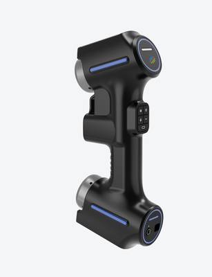
A practical note for evaluation teams: a scanner’s nominal accuracy on a calibration artifact does not automatically translate to the same result on a 2-meter casting in a 30°C shop. Thermal compensation, vibration isolation, and operator technique often determine whether the system meets the tolerance stack-up on real parts. INSVISION offers large-format scanning platforms within this category;
however, the selection process should begin with the measurement task definition, not the hardware.
- What Is 3D Scanning? Principles, Workflow, and Industrial Applications 3D scanning is a digital measurement technology that converts the surface geometry of physical objects into 3D data. This entry covers its working principles, core parameters, industrial use cases, common misconceptions, and related technical…
- What Is a 3D Scanner? Types, Parameters, and Selection Criteria A 3D scanner captures three-dimensional surface data from physical objects and converts geometry, dimensions, and features into digital data for inspection, reverse engineering, and modeling.
- What Is 3D Scanning Accuracy? Accuracy, Repeatability, and Resolution Explained 3D scanning accuracy describes how closely scan data matches an object's actual geometry and dimensions. It is assessed through local accuracy, volumetric accuracy, stitching accuracy, repeatability, and resolution.
- What Is Point Cloud Data? Point Clouds, Meshes, and CAD Models in 3D Scanning Point cloud data is an important raw data format in 3D scanning. It consists of discrete 3D coordinate points that describe object surface geometry and support inspection, reverse engineering, modeling, and archiving.
Hangzhou Insvision Technology Co., Ltd.
Address: Building 1, No. 1399 Liangmu Road, Yuhang District, Hangzhou, Zhejiang 311121, China
Copyright © Hangzhou Insvision Technology Co., Ltd. All rights reserved.
Copyright © Hangzhou Insvision Technology Co., Ltd. All rights reserved.