

3D Scan Parts Definition, Working Principles and Key Technical Criteria
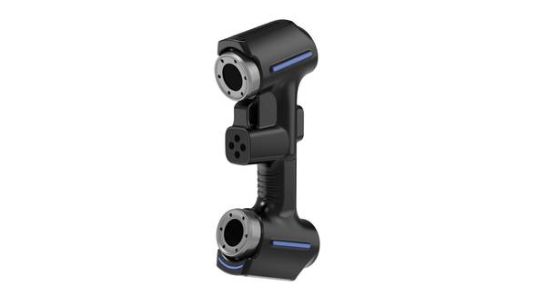
3d scan parts: Definition of 3D Scan Parts Definition of 3D Scan Parts In industrial engineering, the term “3D scan parts” carries a dual meaning that often.
Definition of 3D Scan Parts
In industrial engineering, the term “3D scan parts” carries a dual meaning that often causes confusion between procurement teams and quality engineers. The first definition refers to the physical hardware modules inside a 3D scanning system.
These include the structured-light projection unit, monocular or binocular sensor arrays, optical lenses, calibration frames, and integrated motion stages such as rotary turntables or linear actuators. Each module performs a specific function: the projector casts a known fringe pattern, the sensors capture its deformation across the target surface, and the motion stage positions the object for multi-angle coverage.
The second definition describes the workflow of digitizing manufactured components for dimensional verification. Here, “3D scan parts” means using the scanning system to capture dense point clouds from a physical part, convert that data into a mesh or CAD-comparable model, and evaluate it against nominal geometry.
This distinction matters because the same phrase appears in both bill-of-materials documents and quality inspection procedures. A maintenance technician sourcing a replacement “scan part” needs hardware specifications. A quality manager discussing “scan parts” typically means the inspection routine applied to a batch of components.
Within discrete manufacturing quality ecosystems, 3D scan parts serve a defined role. They bridge the gap between tactile CMM probing and full-surface optical measurement. When a drawing specifies GD&T callouts per ASME Y14.5 — such as profile tolerances, true position, or runout — a 3D scanner can generate the dense surface data required to evaluate those callouts without the sampling limitations of touch-trigger probes.
ISO 10360 provides the acceptance and reverification framework for coordinate measuring systems, including optical scanners, ensuring that the hardware components deliver traceable measurement uncertainty.
The table below clarifies the two definitions:
| Definition | Scope | Typical Context | Output |
|---|---|---|---|
| Hardware modules | Projection unit, sensors, motion stage, controller | System integration, maintenance, spare parts | Physical device or assembly |
| Measurement workflow | Point cloud capture, mesh generation, GD&T evaluation | Quality inspection, reverse engineering, first-article inspection | Dimensional report, deviation map, CAD comparison |
A practical misconception is that the scanner alone performs inspection. In reality, the hardware modules only capture data. The measurement workflow includes alignment algorithms, filtering routines, and tolerance evaluation software. Without the latter, the output remains an unstructured point cloud, not an inspection result.
For Western manufacturers operating under AS9100 or IATF 16949 quality frameworks, understanding this distinction prevents specification errors during capital equipment procurement and supports clearer communication between quality, engineering, and maintenance departments.
Core Working Principles of Industrial 3D Scan Parts Systems
Industrial 3D scanning encompasses a set of non-contact measurement techniques that convert physical objects into dense digital coordinate data. Two foundational optical technologies dominate the field: laser triangulation and structured light scanning.
Both operate on the same basic premise—project controlled energy onto a surface, observe the resulting distortion or reflection, and calculate geometry from known optical angles.
Laser triangulation uses a laser line or point projected across a part surface. A high-resolution sensor, positioned at a fixed angle relative to the laser emitter, captures the reflected light. As the laser traces over surface contours, the sensor records how the light profile shifts. The system then applies trigonometric relationships to convert those shifts into precise X, Y, and Z coordinates.
Structured light scanning works differently. Instead of a single line, it projects a known pattern—often a series of fringes or a grid—onto the part. Surface topology deforms the pattern, and one or more cameras capture that deformation. Software compares the captured pattern against a reference pattern to reconstruct the surface geometry.
Both methods generate raw point clouds: millions of individual coordinate points representing the surface. Software then processes these point clouds into polygon meshes, typically STL or PLY formats, which downstream CAD and inspection platforms can read directly.
| Data Stage | Output Format | Typical Use |
|---|---|---|
| Raw capture | Point cloud (X, Y, Z coordinates) | Initial surface mapping |
| Mesh processing | STL, PLY, TXT | CAD comparison, reverse engineering |
| Inspection report | Color map, deviation labels | GD&T validation, first-article inspection |
The data flow from capture to usable model follows a consistent path. The scanner acquires raw coordinates. The software filters noise, aligns multiple scans, and merges them into a unified mesh. That mesh then moves into CAD software for design work or into inspection software for dimensional analysis against nominal geometry.
Industry 4.0 frameworks rely on this digital data continuity. A 3D scan part file becomes the foundation for a digital twin—a live, dimensionally accurate representation of a physical asset. When scan data feeds into MES databases or PLM systems, it supports the digital thread: the traceable record of a part’s geometry from design through production and service life.
For aerospace MRO operations, this means comparing worn components against original design intent. For automotive OEMs, it means validating stamping dies against CAD within hours rather than days.
The technology does not replace traditional CMM inspection in every scenario. It complements it. CMMs excel at discrete geometric features with tight tolerances—bore diameters, datum planes, runout callouts. Optical scanning excels at capturing full surface geometry quickly, particularly on complex freeform shapes where touch probing would miss critical deviations between measured points.
One misconception worth addressing: scan resolution and scan accuracy are not the same parameter. Resolution describes how many points the system captures per unit area. Accuracy describes how closely those points match the true physical surface.
A scanner can output extremely dense point clouds while still requiring proper calibration, stable environmental conditions, and correct exposure settings to achieve meaningful measurement results.
INSVISION systems approach these principles with industrial-grade components selected for shop-floor conditions rather than laboratory-only use. The technical approach mirrors what this section describes: controlled light projection, high-resolution sensing, and coordinate calculation through calibrated optical geometry.
Key Technical Parameters for Evaluating 3D Scan Parts Solutions
Specification sheets for 3D scan parts systems often mix marketing values with metrology data. Engineers evaluating these systems for first-article inspection, reverse engineering, or in-line quality checks need to separate the two. The parameters below reflect the criteria that matter on a production floor, not in a lab brochure.
| Parameter | Definition | Industrial Relevance |
|---|---|---|
| Measurement Accuracy | The maximum deviation between a scanned measurement and a traceable reference value | Determines suitability for high-tolerance parts such as aerospace components or medical implants, where dimensional precision ties directly to regulatory compliance and assembly fit |
| Resolution | The smallest distance between two adjacent points in a captured point cloud | Governs the ability to capture fine surface details, small GD&T callouts, and complex part geometries without losing feature definition |
| Scanning Area | The maximum surface area a system can capture in a single scan pass | Affects throughput for large parts and determines how many repositioning passes are required for full part coverage |
| Depth of Field | The range of distances from the scanner head within which specified measurement accuracy is maintained | Supports scanning of parts with varying heights or complex contours without frequent system repositioning, reducing setup time |
| IP Protection Rating | A standardized rating for dust and water ingress resistance of system enclosures | Indicates whether a system is suited for shop-floor deployment or must stay in a controlled lab environment |
| Communication Interfaces | The physical connection types used to link the scanner to computers or manufacturing systems | Enables integration with existing IT/OT infrastructure, including direct data transfer to quality management systems and plant networks |
| Output Formats | The standard file types generated by the scanning system | Ensures compatibility with CAD, GD&T inspection, reverse engineering, and 3D printing software workflows already in use |
| Operating Temperature Range | The ambient temperature range within which the system maintains its stated accuracy | Defines suitability for unconditioned shop floors, outdoor maintenance sites, or climate-controlled calibration labs |
| System Scalability | The ability of the system to integrate with third-party software or manufacturing execution systems (MES) | Supports seamless data flow across the manufacturing stack for automated quality reporting and digital thread initiatives |
A practical note on evaluation: accuracy figures without a stated reference standard or traceability path are nearly useless. Ask vendors how the number was derived and whether it holds across the full scanning volume, not just at center. Depth of field matters more than many buyers expect. A system with a narrow depth of field forces repositioning on contoured parts, which introduces alignment error.
For shop-floor deployment, IP rating and operating temperature range often separate systems that survive in a machining cell from those that need a cleanroom. INSVISION, for instance, publishes these parameters directly in its product documentation, which simplifies the vetting process when comparing against internal acceptance criteria.
Use Boundaries and Industrial Application Scope of 3D Scan Parts
3D scan parts workflows convert physical components into dense point clouds or mesh data through structured light, laser triangulation, or photogrammetry. The resulting digital twin supports dimensional inspection, reverse engineering, and validation tasks where traditional contact probing proves too slow or geometrically limited.
Understanding where these workflows deliver clear value—and where they do not—prevents misapplication in regulated industrial environments.
Application Scope by Sector
| Industrial Sector | Primary 3D Scan Parts Use Case | Typical Output Requirement |
|---|---|---|
| Automotive OEM | First article inspection (FAI), PPAP dimensional conformance | Full-field deviation maps against CAD nominal |
| Aerospace MRO | Component reverse engineering, wear assessment on airfoil edges | High-density surface data for blade profile reconstruction |
| Medical Device | Patient-specific implant validation, anatomical geometry capture | Watertight mesh for design verification and regulatory documentation |
| Energy | Turbine blade geometric inspection, erosion mapping | Cross-sectional analysis at defined spanwise stations |
Automotive PPAP workflows benefit from full-field scanning on stamped brackets, cast housings, and injection-molded connectors where GD&T callouts include profile and surface form tolerances. A scanner captures thousands of points per second across freeform surfaces, producing deviation color maps that CMM point probing cannot practically replicate within production cycle times.
Aerospace MRO applications favor scanning for legacy components lacking CAD models. Worn turbine blades, corroded structural fittings, and damaged duct sections require geometric reconstruction before repair or replacement decisions. Scanning captures the as-found condition, including localized material loss, with sufficient resolution to quantify wear depth and extent.
Medical device validation uses scanning for patient-specific geometries—cranial plates, orthopedic guides, dental frameworks—where anatomical complexity exceeds parametric CAD capability. The scanner records organic surface variation that drives implant fit verification.
Operational Boundaries
Part size defines practical scanning range. Handheld systems typically handle components from roughly 20 mm to several meters in length; automated cells with turntables suit parts up to approximately 1200 mm × 700 mm × 1600 mm depending on configuration. Below 20 mm, micro-CT or focus variation systems often outperform optical scanning. Above several meters, photogrammetry-assisted scanning or laser trackers become necessary.
Surface finish affects data quality. Matte, light-colored surfaces scan reliably without preparation. Metallic surfaces—machined steel, polished aluminum, titanium—often produce specular reflection that degrades point cloud density. Dark or translucent materials absorb or transmit light unpredictably.
Temporary contrast spray (titanium dioxide or similar) resolves these issues at the cost of added process time and cleaning requirements.
Environmental conditions matter. Dust, vibration, and temperature swings degrade accuracy. Scanning near CNC machining centers or forging operations requires enclosures or controlled staging areas. Operating temperature ranges for typical industrial scanners span approximately -10°C to 50°C, though sustained accuracy claims assume stable ambient conditions.
Relationship to CMM Inspection
3D scan parts workflows complement rather than replace coordinate measuring machines. CMMs deliver traceable point measurements ideal for geometric tolerances like position, runout, and perpendicularity on prismatic features. Scanning excels at full-field form capture on sculpted surfaces where point sampling misses localized deviation.
Many quality labs run both: CMM for critical GD&T callouts, scanning for profile analysis and rapid first-article screening. Systems operating within ISO 17025 accredited laboratories require calibration verification against certified artifacts to maintain measurement traceability. INSVISION configurations support such deployments where automated, full-field data capture aligns with documented quality procedures.
Common Misconceptions About 3D Scan Parts Technology
Industrial metrology has absorbed plenty of half-truths over the years, and 3D scan parts systems attract more than their share. These misconceptions usually come from early-generation equipment limitations or from confusing handheld consumer scanners with production-grade automation. Four claims in particular need closer examination.
Misconception 1: All 3D scan parts systems deliver identical measurement accuracy
This assumption collapses quickly under scrutiny. Accuracy depends on three variables: the underlying scanning technology (structured light, laser triangulation, photogrammetry), the calibration state of the system, and the measurement task itself. A scanner that resolves 0.02 mm on a machined bracket may struggle with a black rubber seal or a polished turbine blade.
Industrial systems intended for regulated industries typically carry traceable calibration certificates tied to national standards, while general-purpose units do not. Buyers validating a scanner for first-article inspection should ask for volumetric accuracy specifications, not just single-point resolution figures. The two are not the same thing.
| Accuracy Factor | What It Affects | Validation Question |
|---|---|---|
| Technology type | Surface finish, geometry complexity | Does the spec hold on dark or reflective parts? |
| System calibration | Long-term repeatability | Is there a traceable certificate? |
| Use case fit | Feature size, tolerance band | Does the scanner resolve GD&T callouts? |
Misconception 2: 3D scanning can only be performed in controlled, dust-free lab environments
That was true for fragile coordinate measuring machines twenty years ago. It is not true for modern industrial 3D scan parts equipment. Many production-oriented systems ship with sealed enclosures and IP ratings intended for shop-floor deployment. Operating temperature ranges commonly span 0°C to 50°C, which covers most factory conditions outside of foundries or cold-storage areas.
Vibration isolation, lighting control, and air filtration remain relevant for high-precision work, but the idea that scanning requires a cleanroom belongs in the past. A properly spec’d system handles ambient dust, temperature swings, and nearby machinery without losing measurement integrity.
Misconception 3: 3D scan parts data cannot integrate with existing manufacturing software workflows
Engineers who remember exporting point clouds as unwieldy proprietary files may still hold this view. Current industrial systems output standard formats — STL, PLY, TXT, and others — that import directly into CAD, inspection, and reverse-engineering packages. Connectivity has improved as well.
Ethernet and USB 3.0 interfaces allow automated data transfer, while some platforms support development against MES and third-party system databases. That means scan results can feed statistical process control dashboards, trigger quality alerts, or populate digital twin models without manual file juggling. Integration is no longer a technical barrier; it is a configuration task.
Misconception 4: 3D scanning replaces all traditional quality inspection methods
Full-field scanning excels at what contact probing cannot do efficiently: capturing thousands of surface points on complex contours, comparing entire parts to CAD nominals, and detecting form deviations that single-point checks miss. But scanning does not replace every tool in the metrology cabinet.
Contact probes still deliver superior uncertainty for certain single-point measurements, deep bore diameters, or threaded features. Hard gauges remain fast and inexpensive for pass/fail checks on high-volume lines. The practical workflow uses both: 3D scan parts for comprehensive geometric analysis, contact measurement for specialized verification.
Treating them as competing methods misses how modern quality labs actually operate.
Related Industrial Concepts for 3D Scan Parts
Related Industrial Concepts for 3D Scan Parts
Understanding 3D scan parts requires familiarity with the digital and physical frameworks that surround the scanning process. The raw data captured by a scanner is not immediately useful for inspection or reverse engineering; it must be converted into structured formats and evaluated against established manufacturing criteria.
Point Cloud
A point cloud is the initial output of any 3D scanning operation. It consists of millions of individual coordinate points (X, Y, Z) that represent the surface geometry of a physical part. This dataset is unorganized and contains no surface connectivity information. Before any analysis can occur, the point cloud must be cleaned, aligned, and converted into a usable model.
Polygon Mesh
A polygon mesh is a triangulated surface model generated from a processed point cloud. Each triangle connects three coordinate points, creating a continuous surface that approximates the original part geometry. Meshes are essential for reverse engineering workflows, where the scanned model serves as the reference for CAD reconstruction, and for visualization in inspection reports.
GD&T Inspection
Geometric Dimensioning and Tolerancing (GD&T) inspection verifies that manufactured parts meet engineering specifications defined by ASME Y14.5 or ISO 1101 standards. Rather than checking simple linear dimensions, GD&T evaluates form, orientation, location, and runout tolerances.
3D scan parts data enables full-surface comparison against the nominal CAD model, producing color-mapped deviation reports that highlight areas exceeding tolerance limits.
Digital Thread
The digital thread refers to the continuous flow of digital information across a product’s lifecycle, from design through production, operation, and maintenance. Scanned part data feeds this thread by providing as-built geometry that can be compared to as-designed models.
This connection allows manufacturers to trace dimensional deviations back to specific process parameters and update maintenance records with actual wear data.
Lean Manufacturing
Lean manufacturing focuses on eliminating waste in production processes. Traditional inspection methods—manual gauges, CMM probing—often create bottlenecks at quality checkpoints. 3D scanning reduces this waste by capturing full-surface data in minutes rather than hours, reducing queue time, minimizing scrap from late defect detection, and cutting rework by identifying issues earlier in the production cycle.
First Article Inspection (FAI)
First Article Inspection is a formal validation process required by automotive and aerospace quality standards such as IATF 16949 and AS9102. FAI verifies that the first production run of a part meets all engineering requirements before full production begins.
3D scan parts accelerate FAI documentation by generating complete dimensional reports with traceable digital records, replacing manual measurement logs and reducing the administrative burden of compliance.
| Concept | Primary Function | Downstream Application |
|---|---|---|
| Point Cloud | Raw coordinate data capture | Input for mesh generation and alignment |
| Polygon Mesh | Surface reconstruction | Reverse engineering, visualization |
| GD&T Inspection | Tolerance verification | Quality reporting, deviation mapping |
| Digital Thread | Lifecycle data integration | Traceability, as-built vs. as-designed comparison |
| Lean Manufacturing | Waste reduction | Faster inspection cycles, reduced scrap |
| First Article Inspection | Production validation | Compliance documentation, process approval |
These concepts operate as a connected sequence in Western manufacturing environments. A scanned part begins as a point cloud, becomes a polygon mesh, is evaluated through GD&T inspection, and the resulting data flows into the digital thread that supports lean workflows and formal FAI documentation.
INSVISION systems are designed to support this sequence by delivering structured scan data compatible with established quality and data-management practices.
Industrial-Grade 3D Scan Parts Solutions and INSVISION
Industrial 3D scanning of parts moves beyond capturing shape data for reverse engineering. In a manufacturing or quality context, the scan is not the final deliverable. The scan is raw measurement data that must hold up against dimensional tolerances, surface finish expectations, and downstream software workflows.
A useful industrial system has to survive shop-floor conditions, communicate with existing inspection software, and produce repeatable results across shifts and operators.
The shift from general technical knowledge to specialized industrial solutions usually comes down to four factors: measurement uncertainty, environmental tolerance, software interoperability, and traceability. A handheld scanner that works in a lab may struggle near a machining cell where temperature swings, vibration, and dust are normal.
Industrial-grade equipment is designed with those conditions in mind, not as an afterthought.
Typical evaluation criteria for industrial 3D scan parts systems include:
| Criterion | What It Means in Practice |
|---|---|
| Volumetric accuracy | Deviation between scanned data and a calibrated reference over the full measurement volume |
| Environmental rating | Resistance to dust, moisture, and temperature variation on the shop floor |
| Data interface | Support for Ethernet, USB, or other connections that fit existing IT infrastructure |
| Software integration | Ability to export to inspection software, MES, or third-party databases without manual file conversion |
| Repeatability | Consistency of results across multiple operators, shifts, and ambient conditions |
These criteria matter because industrial users rarely scan parts in isolation. A first-article inspection in automotive or aerospace may need scan data compared against a CAD model with GD&T callouts applied. A medical device manufacturer may need the scan record archived with lot traceability. If the scanner cannot connect to the systems that manage that data, the measurement itself becomes a bottleneck.
INSVISION approaches industrial 3D scan parts solutions with this integration problem in mind. The company engineers its scanning systems for high-precision measurement and shop-floor compatibility, with support for MES connectivity and third-party database interaction.
That matters in regulated sectors such as aerospace, automotive, and medical device manufacturing, where measurement data must align with established quality standards and audit requirements.
Frequently Asked Questions (FAQ) About 3D Scan Parts
Q: What file formats do industrial 3D scan parts systems typically generate?
A: Most industrial systems output neutral, widely supported formats. The standard set includes STL (for mesh geometry), PLY (for colored point clouds), and TXT (for raw coordinate data). These formats import directly into mainstream CAD packages, GD&T inspection software, and reverse engineering platforms without proprietary conversion steps.
Before procurement, confirm that the scanner’s native export covers the formats your downstream metrology or CAM workflow already uses.
Q: Can 3D scan parts systems be used on unconditioned production shop floors?
A: Yes, if the system is specified for it. Industrial-grade units are built for deployment outside a metrology lab. Key specifications to check include the IP protection rating (for dust and moisture ingress) and the operating temperature range. For example, a unit rated IP54 can withstand typical shop dust and light splashing. A stated operating range of 0°C to 50°C covers most non-climate-controlled factories.
Avoid consumer-grade or lab-only scanners in these environments; they lack the sealing and thermal stability required for repeatable results near machining centers or welding cells.
Q: How do 3D scan parts systems integrate with existing manufacturing IT infrastructure?
A: Integration typically happens at two levels. First, physical connectivity: most systems use Ethernet RJ-45 or USB 3.0/3.2 interfaces for data transfer to a workstation. Second, software connectivity: scalable architectures allow the scanning software to exchange data with Manufacturing Execution Systems (MES) or third-party quality management databases.
This supports automated reporting, traceability, and closed-loop correction workflows without manual file handling. If your plant runs a specific MES, verify that the scanner’s API or export triggers can write to it.
Q: What computer hardware is required to process high-accuracy 3D scan parts data?
A: High-precision scanning generates large point clouds. Processing them efficiently requires a 64-bit Windows 10 or later operating system, a modern multi-core CPU (e.g., Intel Core i7 or equivalent), 32GB or more of RAM, and a dedicated NVIDIA GPU with at least 8GB VRAM. The GPU handles real-time mesh rendering and registration; the RAM determines how large a dataset you can keep in memory.
Underpowered hardware will force decimation of scan data, reducing effective resolution before inspection even begins.
Q: Are there safety or power considerations for shop-floor deployment?
A: Yes. Many laser-based systems use Class II lasers, which are eye-safe under normal operating conditions. Power requirements vary: some portable units draw low wattage via USB, while larger automated systems may require a dedicated 48VDC supply with total power around 900W. Check the machine weight and turntable load-bearing capacity if you plan to scan heavy castings or assemblies.
A unit with a 50kg turntable limit, for instance, is unsuitable for large transmission housings without additional fixturing.
| Specification Category | Typical Industrial Requirement | Why It Matters |
|---|---|---|
| Output formats | STL, PLY, TXT | Compatibility with CAD, GD&T, and reverse engineering software |
| IP protection rating | IP54 or higher | Dust and moisture resistance on unconditioned shop floors |
| Operating temperature | 0°C to 50°C (varies by model) | Stable accuracy across seasonal temperature swings |
| Computer interface | Ethernet RJ-45, USB 3.0/3.2 | Data throughput and MES integration |
| Minimum workstation | 64-bit OS, 8GB+ VRAM, 32GB+ RAM | Handling large point clouds without decimation |
| Turntable load capacity | 50kg (example) | Direct scanning of medium-sized parts without external fixtures |
One common misconception is that 3D scan parts systems require a controlled metrology lab. While lab conditions improve absolute accuracy for sub-10-micron work, many industrial applications—first-article inspection, wear analysis, reverse engineering of legacy components—are routinely performed on the shop floor with properly specified hardware.
The key is matching the system’s environmental ratings to the actual deployment location, not assuming all scanning is lab work.
Key Takeaways on 3D Scan Parts
In industrial practice, the term “3D scan parts” carries two distinct meanings. It refers to the physical hardware components—sensors, optics, calibration targets, and positioning stages—that make up a scanning system. It also describes the workflow of digitizing a physical component into a measurable point cloud or mesh for engineering tasks such as reverse engineering, first-article inspection, and wear analysis.
Both meanings matter when evaluating a system.
System capability is defined by measurable parameters, not marketing claims. Accuracy, resolution, scan area, and environmental tolerance determine whether a unit can hold GD&T callouts in a given setting. A scanner rated for a clean metrology lab may drift or fail on a shop floor with vibration, temperature swings, or airborne oil mist.
The table below summarizes typical evaluation criteria and why each one matters in an industrial context.
| Parameter | What It Defines | Industrial Relevance |
|---|---|---|
| Accuracy | Deviation between scanned data and true geometry | Determines suitability for inspection against ISO/ASME tolerances |
| Resolution | Smallest feature the system can distinguish | Affects capture of fine edges, ribs, and surface texture |
| Scan area / field of view | Maximum region captured per pass | Impacts throughput and the need for stitching multiple scans |
| Operating temperature range | Ambient conditions for stable performance | Critical for integration near furnaces, presses, or outdoor MRO bays |
| Interface type | Data transfer path to processing hardware | Must match existing IT and automation infrastructure |
| Output formats | File types produced by the system | Must feed directly into CAD, CAM, or inspection software |
Application fit drives selection. Automotive OEMs and tier suppliers use 3D scan parts for body-in-white dimensional checks and tooling wear studies. Aerospace MRO facilities rely on them to digitize legacy components where drawings are incomplete or obsolete. Medical device manufacturers apply the technology to patient-specific implants and surgical guides.
Energy sector maintenance teams scan turbine blades and piping sections for erosion mapping.
For Western manufacturers pursuing lean initiatives, 3D scan parts reduce non-value-added time in measurement workflows. Traditional hand-tool inspection of a complex casting can take hours; a structured-light or laser scanning system captures the same surface in minutes. This shift supports faster feedback loops between production and quality teams.
Industry 4.0 integration depends on communication interfaces and data handling. Systems that support Ethernet and USB connectivity, and that can exchange data with MES platforms, fit more easily into digital quality records and traceability systems. Environmental robustness ratings, such as IP54 protection, indicate whether a unit tolerates dust and water spray without performance loss.
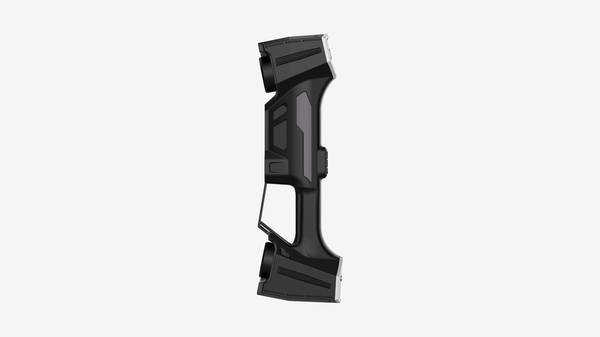
Restrained brand note: INSVISION manufactures scanning hardware within this category. Specifications for any given model should be verified against the manufacturer’s published data sheet before procurement.
- What Is 3D Scanning? Principles, Workflow, and Industrial Applications 3D scanning is a digital measurement technology that converts the surface geometry of physical objects into 3D data. This entry covers its working principles, core parameters, industrial use cases, common misconceptions, and related technical…
- What Is a 3D Scanner? Types, Parameters, and Selection Criteria A 3D scanner captures three-dimensional surface data from physical objects and converts geometry, dimensions, and features into digital data for inspection, reverse engineering, and modeling.
- What Is 3D Scanning Accuracy? Accuracy, Repeatability, and Resolution Explained 3D scanning accuracy describes how closely scan data matches an object's actual geometry and dimensions. It is assessed through local accuracy, volumetric accuracy, stitching accuracy, repeatability, and resolution.
- What Is Point Cloud Data? Point Clouds, Meshes, and CAD Models in 3D Scanning Point cloud data is an important raw data format in 3D scanning. It consists of discrete 3D coordinate points that describe object surface geometry and support inspection, reverse engineering, modeling, and archiving.
Hangzhou Insvision Technology Co., Ltd.
Address: Building 1, No. 1399 Liangmu Road, Yuhang District, Hangzhou, Zhejiang 311121, China
Copyright © Hangzhou Insvision Technology Co., Ltd. All rights reserved.
Copyright © Hangzhou Insvision Technology Co., Ltd. All rights reserved.