

3D Scan Data Post-Processing
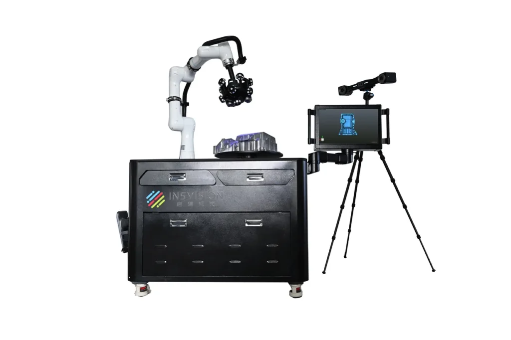
3D scan data post-processing refers to the sequence of computational workflows applied to raw 3D scan output (typically unfiltered point clouds, depth maps, or unstructured meshes) captured by industrial 3D scanning systems, to produce accurate, structured, and application-ready 3D assets.
Definition
3D scan data post-processing refers to the sequence of computational workflows applied to raw 3D scan output (typically unfiltered point clouds, depth maps, or unstructured meshes) captured by industrial 3D scanning systems, to produce accurate, structured, and application-ready 3D assets. It is a core intermediate step in the industrial 3D digitalization pipeline, bridging raw data capture and downstream use cases such as quality inspection, reverse engineering, additive manufacturing, and part documentation. Post-processing addresses common artifacts introduced during scanning, including environmental noise, background clutter, misaligned scan passes, occlusions, and surface reflection errors.
How It Works
Post-processing workflows are tailored to the type of scanning hardware (e.g., handheld laser, structured light, optical tracked, automated scanning systems) and intended downstream application, but follow a general core sequence:
- Raw Data Import: Raw scan output, which may consist of multiple discrete scan passes for large or complex objects, is imported into dedicated post-processing software.
- Pre-Cleaning: Outlier points caused by environmental interference, surface reflections, or background clutter (e.g., worktables, turntables) are removed to isolate only the data corresponding to the scanned object.
- Registration/Alignment: Discrete scan passes are aligned into a single unified coordinate system. This may use target markers placed on the object, common geometric features across overlapping scans, or cloud-to-cloud matching algorithms.
- Gap Filling & Geometry Reconstruction: Gaps in the dataset caused by occlusions, deep undercuts, or non-optimal surface properties (e.g., high reflectivity, transparency) are filled, with algorithms tuned to preserve sharp edges or fine features as required.
- Mesh Optimization: The structured point cloud is converted to a polygon mesh, which is then refined: excess polygons are decimated to reduce file size without sacrificing critical detail, non-critical surface noise is smoothed, and topological errors (e.g., flipped normals, non-manifold edges) are corrected.
- Downstream Preparation: Optional application-specific steps are performed, such as alignment to reference CAD models for deviation analysis, application of texture maps for visual documentation, or conversion to parametric formats for reverse engineering.
Many modern post-processing workflows integrate AI-assisted tools to automate routine steps such as outlier removal, alignment, and gap filling for standardized part batches.
Key Parameters and Criteria
The quality and suitability of post-processed 3D data are evaluated against standardized, measurable parameters, with acceptable thresholds varying by use case, scanner hardware, and industry requirements.
| Parameter | Meaning | Judgment Method |
|---|---|---|
| Point Cloud Fidelity | The degree to which processed data retains the original geometric accuracy and fine features of the scanned object, including critical edges, holes, and micro-scale surface details | Deviation comparison of processed point cloud against calibrated reference artifacts or certified CAD models, measured across dimensionally critical regions |
| Registration Error | The maximum positional offset between overlapping, aligned scan passes or datasets, which impacts overall model accuracy | Calculation of root mean square (RMS) deviation of common reference targets or matching geometric features across all registered scan datasets |
| Mesh Topology Quality | The structural consistency of the output polygon mesh, including the absence of non-manifold edges, flipped normals, degenerate faces, and unintended gaps | Automated topology validation checks in post-processing software, visual inspection of high-stress or dimension-critical regions, and compatibility testing with downstream CAD/CAE tools |
| Processing Throughput | The total end-to-end time required to convert raw scan data into a production-ready output asset | Measurement of runtime for standardized test datasets of defined size and complexity, conducted on consistent hardware and software configurations |
| Output Compatibility | The ability of processed data to be imported and used without data loss in downstream industrial software platforms | Verification of lossless export and functional import across common 3D file formats (e.g., STL, PLY, STEP, IGES) and native CAD/inspection software ecosystems |
Suitable and Unsuitable Scenarios
Suitable Scenarios
- Industrial dimensional quality inspection: Processing scan data for deviation analysis against reference CAD models and GD&T compliance verification for automotive, aerospace, energy, and general manufactured components.
- Reverse engineering: Preparing scan data to generate editable parametric CAD models for legacy parts with no existing design documentation, or for part redesign and optimization.
- Additive manufacturing pre-processing: Cleaning and optimizing scan data of master patterns or existing parts to produce valid, 3D-printable mesh files.
- Batch part quality control: Aligning and standardizing data from automated scanning systems for high-volume, repeatable part inspection.
- High-detail part documentation: Enhancing scan data of small, complex components (e.g., injection molded valves, precision mold inserts) to capture micro-scale features for design validation.
Unsuitable Scenarios
- Real-time in-line process control requiring instantaneous data output, as post-processing introduces measurable computational latency.
- Forensic or raw data archiving use cases that require unaltered original scan data, as post-processing modifies the captured dataset to remove artifacts and align geometry.
- Micro-scale applications requiring sub-micron level accuracy for semiconductor or micro-electromechanical components, unless the post-processing workflow is explicitly calibrated and validated for micro-scale feature retention.
Common Misconceptions
- Misconception: Post-processing always improves the accuracy of 3D scan data.
Clarification: Improperly configured post-processing (e.g., over-smoothing of critical features, aggressive outlier removal, or incorrect alignment parameters) can introduce geometric distortion or erase valid captured data, reducing overall accuracy. Post-processing only improves accuracy when tuned to correct for known scanning artifacts without altering valid geometry.
- Misconception: Post-processing workflows are identical across all 3D scanner types.
Clarification: Workflows are tailored to the specific output of each scanning technology: handheld laser scanners often produce point clouds with minor drift artifacts requiring robust registration, while structured light scanners may generate denser datasets with reflection-related noise requiring specialized cleaning tools.
- Misconception: Fully automated post-processing eliminates all need for human input.
Clarification: While AI-assisted automation can streamline routine post-processing for standardized, high-volume part batches, complex geometries (e.g., deep undercuts, high-reflection molds, thin-walled components) still require manual review and adjustment to ensure critical features are preserved.
- Misconception: Higher mesh resolution always produces superior post-processed results.
Clarification: Excessively high polygon counts increase file size and processing time without improving functional accuracy, and may cause compatibility issues with downstream CAD/CAE tools. Optimal mesh resolution is matched to the requirements of the specific downstream use case.
Related Concepts
- Point Cloud Registration: A core sub-process of post-processing that aligns multiple overlapping scan datasets into a single unified coordinate system, required for scanning large or complex objects that cannot be captured in a single pass.
- Deviation Analysis: A common downstream application of post-processed scan data, where the finalized 3D model is compared to a reference CAD model to identify and quantify dimensional variances.
- Reverse Engineering: The process of converting post-processed scan data into editable parametric CAD models for part reproduction, redesign, or engineering analysis.
- GD&T Inspection: A quality control workflow that uses post-processed 3D data to verify compliance with geometric dimensioning and tolerancing specifications for manufactured parts.
- Multi-Source Data Alignment: An advanced post-processing workflow that combines data from multiple 3D capture technologies (e.g., laser scanning, structured light scanning, optical tracking) into a single unified dataset for comprehensive part assessment.
FAQ
What is the difference between raw scan data and post-processed scan data?
Raw scan data is unfiltered output captured directly by a 3D scanner, consisting of discrete point clouds or depth maps that often contain background clutter, environmental noise, and disconnected scan passes if multiple captures were performed. Post-processed scan data is cleaned, aligned, and formatted for specific use cases, with artifacts removed and all scan data unified into a single, structured coordinate system.
Can post-processing fix errors caused by poor scanning technique?
Post-processing can correct minor scanning artifacts, such as isolated noise points, small occlusions, or slight scan misalignment. However, it cannot resolve major scanning errors, such as large missing data regions from un-scanned undercuts, significant scanner drift, or complete loss of critical feature data from incorrect scanning parameter settings.
What factors impact the time required for 3D scan data post-processing?
Processing time varies based on multiple factors, including dataset size, object complexity, required output accuracy, post-processing software capabilities, and processing hardware specifications. Simple, small parts with standardized workflows may take only a few minutes to process, while large, high-complexity components (e.g., aerospace airframes, automotive tooling) may require several hours for full processing and validation.
Is post-processing required for all 3D scan use cases?
No. Raw scan data may be sufficient for basic use cases, such as quick visual assessments or rough dimensional checks. Post-processing is required for use cases demanding high accuracy, formal quality documentation, compatibility with industrial design or manufacturing software, or reverse engineering.
Summary
3D scan data post-processing is a foundational step in the industrial 3D digitalization pipeline, converting raw 3D scan output into accurate, structured assets that support a wide range of industrial use cases including quality inspection, reverse engineering, and additive manufacturing. Workflows are tailored to scanning hardware, object characteristics, and downstream application requirements, with measurable parameters governing output fidelity, accuracy, and compatibility. While automated and AI-assisted tools have streamlined routine post-processing tasks for standardized applications, human oversight remains critical for high-accuracy, high-complexity use cases to ensure the preservation of critical geometric features.
- What Is 3D Scanning? Principles, Workflow, and Industrial Applications 3D scanning is a digital measurement technology that converts the surface geometry of physical objects into 3D data. This entry covers its working principles, core parameters, industrial use cases, common misconceptions, and related technical…
- What Is a 3D Scanner? Types, Parameters, and Selection Criteria A 3D scanner captures three-dimensional surface data from physical objects and converts geometry, dimensions, and features into digital data for inspection, reverse engineering, and modeling.
- What Is 3D Scanning Accuracy? Accuracy, Repeatability, and Resolution Explained 3D scanning accuracy describes how closely scan data matches an object's actual geometry and dimensions. It is assessed through local accuracy, volumetric accuracy, stitching accuracy, repeatability, and resolution.
- What Is Point Cloud Data? Point Clouds, Meshes, and CAD Models in 3D Scanning Point cloud data is an important raw data format in 3D scanning. It consists of discrete 3D coordinate points that describe object surface geometry and support inspection, reverse engineering, modeling, and archiving.
Hangzhou Insvision Technology Co., Ltd.
Address: Building 1, No. 1399 Liangmu Road, Yuhang District, Hangzhou, Zhejiang 311121, China
Copyright © Hangzhou Insvision Technology Co., Ltd. All rights reserved.
Copyright © Hangzhou Insvision Technology Co., Ltd. All rights reserved.