

3D Laser Triangulation Core Principles, Key Parameters, and Industrial Boundaries
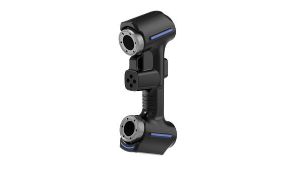
3d laser triangulation: Definition of 3D Laser Triangulation Definition of 3D Laser Triangulation 3D laser triangulation is a non-contact optical measurement.
Definition of 3D Laser Triangulation
Definition of 3D Laser Triangulation
3D laser triangulation is a non-contact optical measurement technique that determines surface geometry by projecting a laser line or point onto a target and observing its deformation from a known offset angle using a camera or position-sensitive detector. The laser source, sensor, and measured point form a triangle, hence the term.
When the projected laser intersects a surface at varying heights, the reflected light shifts position on the sensor. The system calculates the Z-axis displacement from this lateral shift using calibrated trigonometric relationships. A complete 3D profile emerges when the sensor or object moves along a scanning axis, stitching sequential cross-sections into a dense point cloud.
Scenario Snapshot
A practical way to read the article is through this scenario:
- Definition of 3D Laser Triangulation: 3D laser triangulation is a non-contact optical measurement technique that determines surface geometry by projecti…
- Core Operating Principle of 3D Laser Triangulation: 3D laser triangulation is a geometric measurement method.
- Z = (B × f) / (p + B × tan θ): Where B is the baseline separation, f is the effective focal length of the imaging lens, p is the measured pixel d…
Unlike coordinate measuring machines (CMMs) that require physical probing, 3D laser triangulation captures dimensional data without touching the part. This distinction matters for soft, deformable, or thermally sensitive materials where contact would alter the measurement itself.
The technique also operates at high acquisition rates, making it suitable for inline inspection where parts move continuously on conveyors or robotic cells.
Within industrial quality control, 3D laser triangulation supports tasks such as surface defect detection, weld seam inspection, gap-and-flush measurement on automotive body panels, and dimensional verification of machined features.
The method aligns with ISO 10360-series acceptance tests for coordinate measuring systems and ASME Y14.5 GD&T callouts, where extracted point clouds are compared against nominal CAD geometry to evaluate form, profile, and positional tolerances.
The table below summarizes core characteristics that distinguish 3D laser triangulation from other optical and contact methods.
| Parameter | 3D Laser Triangulation | Structured Light | Contact CMM |
|---|---|---|---|
| Measurement principle | Laser line/point displacement on sensor | Projected fringe or grid patterns | Physical stylus contact |
| Contact with part | None | None | Yes |
| Typical acquisition speed | High (kHz profile rates) | Medium to high | Low (point-by-point) |
| Sensitivity to surface finish | Moderate; affected by specular reflections | Moderate to high | Low |
| Suitability for soft materials | Excellent | Excellent | Poor |
| Common industrial use | Inline profile scanning, weld inspection, gap measurement | Reverse engineering, area scanning | Reference metrology, calibration |
One common misconception is that 3D laser triangulation equals full-field scanning. In practice, a single triangulation sensor captures one profile at a time. Full surface coverage requires relative motion between the sensor and part, whether through linear stages, robots, or part rotation.
This distinction affects system integration decisions, particularly when specifying encoder synchronization for accurate point-cloud reconstruction at high traverse speeds.
The technique fits naturally into Industry 4.0 frameworks. Profile data streams from triangulation sensors feed statistical process control (SPC) systems, enabling real-time trend monitoring and closed-loop correction without interrupting production flow. Lean manufacturing environments benefit from the elimination of dedicated metrology fixtures and the reduction of non-value-added handling associated with batch inspection.
INSVISION supplies 3D laser triangulation sensors operating at 520 nm wavelength with Class 3R laser output, a specification relevant to integrators evaluating eye-safety enclosures and machine guarding requirements.
Core Operating Principle of 3D Laser Triangulation
3D laser triangulation is a geometric measurement method. It establishes a known triangle between a laser emitter, a target surface point, and an imaging sensor. The technique works because the position of reflected laser light on the sensor shifts predictably as the distance to the target changes. That positional displacement is the raw signal from which depth is calculated.
The process follows a fixed sequence. First, the laser source projects a point or a line onto the surface being measured. The projected feature follows the surface contour, not the sensor’s field of view. Second, the imaging sensor captures the reflected laser spot or line at an angle offset from the projection axis. If the surface moves closer to the sensor, the reflected light appears at one position on the sensor array.
If it moves farther away, the light appears at a different position. Third, system firmware converts that pixel displacement into a physical Z-height value.
The conversion relies on a calibrated baseline distance between the laser and the sensor, plus the known projection and observation angles.
Z = (B × f) / (p + B × tan θ)
Where B is the baseline separation, f is the effective focal length of the imaging lens, p is the measured pixel displacement, and θ is the triangulation angle. Calibration establishes exact values for B, f, and θ for each sensor assembly, accounting for lens distortion and mounting tolerances.
| Parameter | Role in Triangulation | Typical Effect on Accuracy |
|---|---|---|
| Baseline distance (B) | Separation between laser and sensor | Larger baseline improves Z-resolution but increases occlusion risk |
| Triangulation angle (θ) | Angle between projection and observation axes | Steeper angles improve near-range resolution; shallow angles suit tall surfaces |
| Pixel displacement (p) | Measured shift of laser spot on sensor | Sub-pixel interpolation determines ultimate resolution limit |
| Focal length (f) | Lens magnification of reflected light | Longer focal lengths increase sensitivity but shrink field of view |
This geometric approach differs from time-of-flight or interferometric methods. Triangulation does not measure light travel time. It measures spatial position on a detector. That distinction matters in industrial settings: triangulation excels at short-to-mid working distances, typically under one meter, where it delivers micron-level depth resolution. Time-of-flight dominates at longer ranges but resolves coarser depth steps.
A practical consideration for engineers: the triangulation angle creates a shadow zone. Steep surfaces or deep features can block the laser from reaching the sensor, producing missing data. Sensor placement and multi-line projection strategies mitigate this in production environments, but the geometric constraint remains fundamental.
The method supports both single-point and full-line acquisition. Single-point triangulation measures one coordinate per exposure. A laser line, captured across the sensor’s two-dimensional array, yields hundreds of simultaneous Z-values along the line profile. Scanning the line across a part builds a dense 3D point cloud.
This scalability explains why triangulation underpins applications ranging from runout inspection on turned shafts to full-surface digitization of stamped sheet metal.
Accuracy depends on calibration discipline. Baseline drift from thermal expansion, sensor mounting flex, or lens contamination directly corrupts the geometric model. Western manufacturing environments following ISO 10360 or ASME B89.4.19 verification protocols typically require periodic field calibration against traceable reference artifacts.
INSVISION and other industrial sensor suppliers document these calibration intervals for their triangulation hardware, but the geometric principle remains vendor-neutral.
The core advantage is simplicity. A laser, a lens, a sensor array, and a calibrated triangle produce repeatable dimensional data without contact, without moving measurement probes, and without dependence on surface reflectivity beyond the laser wavelength’s response.
That simplicity, combined with sub-pixel processing algorithms, keeps triangulation relevant across automotive OEM, aerospace MRO, and medical device inspection workflows.
Key Performance Parameters for 3D Laser Triangulation Systems
Evaluating a 3D laser triangulation system requires more than a glance at a spec sheet. The performance envelope of these sensors is defined by a set of standardized parameters that directly affect how a system behaves on a production floor, inside a measurement lab, or within an automated inspection cell.
Alignment with metrology frameworks such as ISO 10360 provides a common reference for verifying system capability, but the practical interpretation of those parameters depends heavily on the application.
The table below outlines the core parameter categories used across industrial evaluations. Each parameter carries specific technical meaning and operational consequences.
| Parameter Category | Technical Definition | Industrial Relevance |
|---|---|---|
| Laser Class | Safety classification of the laser source per IEC 60825 and ANSI Z136 standards, indicating potential ocular hazard levels | Determines workplace safety protocols, operator PPE requirements, and suitability for unsupervised automated production environments |
| Laser Wavelength | The specific nanometer wavelength of light emitted by the laser source | Impacts reflectivity performance across common industrial materials (metals, engineering plastics, composites) and measurement reliability across varied surface finishes |
| Scanning Mode Flexibility | Availability of multiple laser line configurations tailored to different measurement tasks | Enables adaptation to diverse part geometries, including deep cavities, fine precision features, and large surface areas, without requiring additional hardware |
| Measurement Precision | The degree of alignment between measured values and the true dimensional value of a target, per ISO 10360 calibration standards | Critical for meeting tight tolerance requirements in aerospace, medical device, and high-precision automotive manufacturing |
| Scan Speed | The rate at which 3D point cloud data is captured, measured in points per unit of time | Aligns with production cycle time requirements for inline quality control and high-volume inspection workflows |
Laser classification is often the first filter applied during system selection. A Class II source permits operation without additional enclosures in many jurisdictions, while a Class 3R source introduces restrictions around direct beam exposure. Wavelength selection follows closely behind.
Shorter wavelengths in the blue-green range interact differently with metallic and dark surfaces than longer red wavelengths, a factor that becomes evident during first-article inspection of machined aluminum or carbon-fiber layups.
Scanning mode flexibility deserves particular attention from engineers responsible for mixed-part production. A system that offers only a single line configuration may struggle when the same cell must inspect both a deep bore and a broad surface panel. Multiple line modes allow the sensor to be reconfigured in software rather than re-engineered in hardware.
INSVISION systems are designed around these evaluation criteria, with specifications documented for laser class, wavelength, and scanning mode options.
Ideal Industrial Use Cases and Operating Boundaries
3D laser triangulation is a non-contact optical measurement method that reconstructs surface geometry by projecting a laser line onto a part and observing its deformation through a calibrated camera at a known angle. The technique converts lateral displacement of the laser stripe into depth information, producing dense point clouds suitable for dimensional analysis.
This principle defines both where the technology delivers strong value and where alternative methods are more appropriate.
Application Fit by Industry
| Industry | Typical Use Case | Measurement Focus |
|---|---|---|
| Automotive OEM | Sheet metal panel inspection, closure gap profiling | Surface deviation, edge break, springback |
| Aerospace MRO | Wear assessment on turbine blades, landing gear components | Material loss, pitting depth, chord profile |
| Medical Device | Implant dimensional verification, orthopedic component validation | Form tolerance, radius conformity, thread geometry |
| Wind Energy | Bearing seat inspection, blade root section quality control | Roundness, surface finish anomalies, bolt hole position |
Operating Boundaries as Fit Criteria
The technology performs best under conditions that are common in these industrial settings. Stable ambient factory lighting — whether controlled LED illumination or enclosed measurement cells — minimizes interference with the projected laser line.
Non-transparent solid industrial materials such as stamped steel, machined titanium, forged aluminum, and composite tooling provide diffuse reflection that returns a clean signal to the sensor. These are not limitations in the negative sense; they are the operating envelope where the measurement principle yields repeatable, traceable results.
Transparent, highly specular, or deeply absorptive surfaces scatter or attenuate the laser line, degrading data quality. In such cases, surface preparation such as matting spray or alternative optical methods may be required. Understanding this boundary helps quality engineers select the right tool for the right inspection task rather than forcing a method outside its reliable range.
Common Misconceptions About 3D Laser Triangulation
Several assumptions about 3D laser triangulation persist among quality and manufacturing teams, often delaying adoption or narrowing its perceived fit. Many of these beliefs do not hold up against the engineering realities of current systems.
One frequent concern is that all triangulation lasers pose unmanageable eye safety risks. The hazard depends on the laser class. While some projector-based systems use Class 3R sources (below 5 mW, not intended for direct eye viewing), other scanning configurations are built around Class II lasers, which are considered eye-safe under normal operating conditions.
The correct question is not “is it safe,” but “what class is specified for this application.”
A second misconception is that triangulation cannot capture deep cavity geometry. This is a matter of optical configuration, not a fundamental limit. Systems that project multiple blue laser lines can scan broad surfaces quickly, while a dedicated single-line mode is often used specifically to reach into deep holes or recesses where multi-line patterns would occlude.
The trade-off is speed versus access, not a binary capability gap.
A third assumption is that the technology only suits manual inspection workflows. In practice, triangulation sensors are routinely integrated into automated cells for in-line dimensional checks, first-article inspection, and GD&T verification. The sensor is a data source; whether the workflow is manual or automated depends on the fixturing, robotics, and software layer around it.
| Misconception | Engineering Reality |
|---|---|
| All systems are unsafe for eyes | Depends on laser class; Class II options exist for eye-safe operation |
| Cannot measure deep cavities | Single-line modes are designed for deep-hole access |
| Only works for manual inspection | Commonly integrated into automated in-line cells |
Evaluating a system should focus on the specific scan mode, laser class, and integration path rather than broad assumptions about the technology itself.
Related 3D Measurement Technologies and Distinctions
Non-contact 3D measurement is not a single technology but a family of optical methods, each tuned to a different balance of speed, resolution, standoff distance, and environmental tolerance. Selecting the wrong approach for a given task usually results in either excessive cost or insufficient data quality.
The three most common techniques encountered in industrial settings are structured light scanning, time-of-flight scanning, and 3D laser triangulation.
The table below summarizes the core distinctions.
| Technology | Core Strength | Typical Measurement Range | Ideal Scenario |
|---|---|---|---|
| Structured Light Scanning | Very high point density and resolution | ~0.1–1 m | Bench-top inspection of small, complex parts in a controlled lab |
| Time-of-Flight (ToF) | Long standoff and rapid capture of large volumes | ~1–100+ m | Surveying, outdoor asset mapping, large-scale scene capture |
| 3D Laser Triangulation | Balanced speed, precision, and robustness | ~0.05–0.5 m | Inline or near-line quality control of mid-sized parts on the factory floor |
Structured light systems project known patterns—often a sequence of fringes or grids—and compute depth from how those patterns deform across the part surface. This approach yields extremely dense point clouds and is well suited to first-article inspection or reverse engineering of small, intricate components.
The trade-off is sensitivity to ambient light and vibration, which confines most structured light work to metrology labs or dedicated inspection cells.
Time-of-flight scanners measure the round-trip travel time of a light pulse to determine distance. Because the measurement is based on timing rather than geometry, these systems can operate at long ranges and cover large areas quickly.
Accuracy is typically in the millimeter range, which is adequate for topographical mapping or large asset condition monitoring but generally insufficient for tight GD&T callouts on machined components.
3D laser triangulation occupies the middle ground. A laser line is projected onto the part, and an offset camera observes the line’s position. Depth is calculated from the known baseline angle between laser and camera. This geometric approach delivers accuracy in the tens of microns while operating at speeds compatible with production cadence.
The technique tolerates factory lighting and vibration better than structured light, making it the standard choice for inline dimensional checks, weld seam inspection, and near-line quality gates on mid-sized parts such as brackets, housings, and castings.
The practical decision is rarely about which method is “better” and more about which constraint dominates the application: resolution, range, or environmental robustness.
INSVISION 3D Laser Triangulation Solution Overview
In the broader landscape of industrial non-contact metrology, 3D laser triangulation remains a foundational measurement principle. It operates by projecting a laser line onto a surface and observing its deformation through a calibrated camera at a known angle. The resulting point cloud forms the basis for dimensional analysis, GD&T verification, and surface defect detection.
The practical value of any triangulation system, however, depends less on the principle itself and more on how the optics, laser source, and scanning logic are configured for specific inspection tasks.
INSVISION develops industrial 3D laser triangulation systems for metrology and quality control applications. The company’s published technical specifications confirm a range of configurations that address common factory-floor constraints. Two attributes are particularly relevant for Western manufacturing environments where operator safety and material compatibility are evaluated early in the capital equipment review.
The first is laser safety classification. INSVISION offers systems with Class II eye-safe laser options, which simplifies integration in open work cells and reduces the administrative burden associated with higher-class laser enclosures. The second is wavelength.
Several INSVISION projector configurations specify a 520 nm green laser source, a wavelength that can perform differently than red lasers on certain reflective or dark surfaces.
Scanning modes vary across the company’s product lines.
| Scanning Mode | Confirmed Laser Line Configuration | Typical Application Context |
|---|---|---|
| Deep Hole Scanning | 1 single blue laser line | Narrow apertures, recessed features, blind holes |
| Precision Scanning | 7 blue laser lines | Dimensional verification, fine feature extraction |
| High-Speed Scanning | 50 blue laser lines | Large-area capture where throughput is critical |
The distinction between single-line and multi-line modes matters in practice. A single line provides a cleaner signal in confined geometries where multiple reflections would otherwise create noise. Multi-line modes increase point density per pass but require more controlled lighting conditions.
The availability of these modes within a single platform, as indicated in INSVISION’s specifications, allows an inspection engineer to select the appropriate trade-off between resolution and cycle time without switching hardware.
For procurement professionals, the relevant evaluation criteria remain unchanged: measurement accuracy under production conditions, repeatability across temperature ranges, and compatibility with existing CMM or CAD-based workflows. A provider’s published laser specifications are one input into that evaluation, not a substitute for first-article validation on representative parts.
Frequently Asked Questions About 3D Laser Triangulation
What laser safety standards apply to industrial 3D laser triangulation systems?
Most industrial triangulation sensors fall under IEC 60825-1 classifications. Class 2/II systems rely on the blink reflex for eye safety and suit open workstations. Class 3R units, typically under 5 mW, are common where higher visibility is needed but require controlled access and signage. The relevant standard for integrating lasers into machinery is ISO 11553.
Facilities must also account for local regulations such as OSHA 29 CFR 1040 in the United States. A key operational point: a 520 nm green laser is visible in daylight, which reduces the temptation for operators to look directly at the source. Always confirm the specific class marking before commissioning a line.
How does 3D laser triangulation support lean manufacturing objectives?
Triangulation replaces hard gages and manual checks with inline measurement. That shift eliminates non-value-added handling and queue time between production and the metrology lab. Engineers can trigger inspection at the point of manufacture, detecting drift before it produces scrap. The data feeds directly into statistical process control, turning dimensional checks from a downstream gate into a real-time process input.
This supports jidoka principles—machines stop when quality deviates, not after a batch runs. Procurement teams also see reduced gage inventory and calibration overhead.
Can 3D laser triangulation data integrate with existing CAD and metrology software?
Yes. Standard outputs include point clouds and mesh formats (STL, PLY) that import directly into CAD packages for reverse engineering or comparison against nominal models. For inspection workflows, data typically exports to metrology software supporting GD&T callouts such as profile, flatness, and runout tolerance. The key is not the sensor itself but the middleware that aligns scanned data to the CAD reference frame.
Most industrial platforms accept generic ASCII or binary point data, so integration rarely requires proprietary software locks.
What material types work best with 3D laser triangulation systems?
| Material Surface | Behavior | Typical Application |
|---|---|---|
| Matte metals, plastics | Excellent diffuse reflection | Machined parts, castings |
| Dark or black surfaces | Reduced return signal | Rubber seals, carbon fiber |
| Polished or mirror-like | Specular reflection; may require coating | Ground shafts, medical implants |
| Transparent or translucent | Laser passes through | Glass, acrylic components |
Matte surfaces return the strongest diffuse signal. Shiny metals scatter light away from the sensor, so engineers often apply a temporary developer spray. Transparent parts generally require alternative optical techniques unless a coating is acceptable. The question for procurement is not “can it scan” but “what surface preparation does the cycle time allow.”
Core Takeaways for Industrial Stakeholders
Core Takeaways for Industrial Stakeholders
3D laser triangulation is an active, non-contact optical measurement method in which a laser emitter projects a point or line onto a surface, and an offset camera observes the projected feature from a known angle. The resulting image displacement, combined with the fixed baseline between emitter and sensor, allows the system to compute height and profile data through trigonometric calculation.
The geometric principle is straightforward: emitter, surface point, and camera form a triangle. When surface height changes, the laser spot shifts across the camera sensor. Calibrated systems convert that pixel shift into a Z-axis measurement. Accuracy depends on baseline distance, lens focal length, pixel resolution, and the angle between laser and camera.
Key performance parameters to evaluate:
| Parameter | What it affects | Industrial relevance |
|---|---|---|
| Standoff distance | Clearance between sensor and target | Part access in fixtures, robot cells |
| Measurement range (Z) | Height variation the sensor can capture | Surface geometry, part tolerance bands |
| Lateral resolution (X/Y) | Smallest feature detectable along the profile | Edge detection, weld seams, microfeatures |
| Laser wavelength and class | Eye safety, material interaction | Operator safety, reflective or dark surfaces |
| Scan rate | Profiles captured per second | Inline inspection speed, cycle time constraints |
Ideal applications include profile measurement of machined edges, weld seam inspection, gap and flush checks on automotive body panels, tire sidewall inspection, and dimensional verification of extruded profiles. The method works best on diffuse surfaces with moderate reflectivity and accessible geometry.
Compared with structured light systems, laser triangulation tolerates ambient illumination better and delivers higher lateral resolution on narrow profiles, though it captures less data per pass. Compared with time-of-flight sensors, triangulation offers far higher precision at close range but loses accuracy as standoff increases.
Compared with confocal or interferometric methods, it is faster and less sensitive to vibration, but cannot match sub-micron resolution.
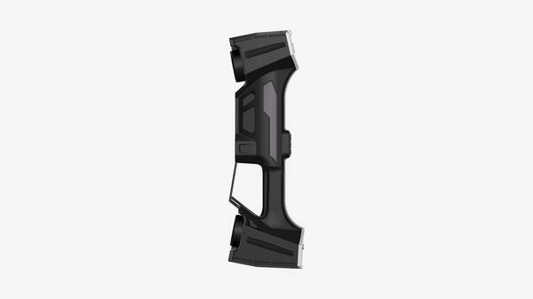
Solution selection should be driven by specific application requirements, tolerance needs, and operational context. A system that works well for first-article inspection may be unsuitable for high-speed inline measurement. Factors such as part accessibility, surface finish, environmental lighting, and data throughput should be evaluated before committing to a platform.
INSVISION provides industrial 3D scanning and measurement hardware for teams evaluating these trade-offs in production environments.
- What Is 3D Scanning? Principles, Workflow, and Industrial Applications 3D scanning is a digital measurement technology that converts the surface geometry of physical objects into 3D data. This entry covers its working principles, core parameters, industrial use cases, common misconceptions, and related technical…
- What Is a 3D Scanner? Types, Parameters, and Selection Criteria A 3D scanner captures three-dimensional surface data from physical objects and converts geometry, dimensions, and features into digital data for inspection, reverse engineering, and modeling.
- What Is 3D Scanning Accuracy? Accuracy, Repeatability, and Resolution Explained 3D scanning accuracy describes how closely scan data matches an object's actual geometry and dimensions. It is assessed through local accuracy, volumetric accuracy, stitching accuracy, repeatability, and resolution.
- What Is Point Cloud Data? Point Clouds, Meshes, and CAD Models in 3D Scanning Point cloud data is an important raw data format in 3D scanning. It consists of discrete 3D coordinate points that describe object surface geometry and support inspection, reverse engineering, modeling, and archiving.
Hangzhou Insvision Technology Co., Ltd.
Address: Building 1, No. 1399 Liangmu Road, Yuhang District, Hangzhou, Zhejiang 311121, China
Copyright © Hangzhou Insvision Technology Co., Ltd. All rights reserved.
Copyright © Hangzhou Insvision Technology Co., Ltd. All rights reserved.