

Automated 3D Inspection System: Key Checks Before Equipment Selection
Automated 3d inspection system: verify part presentation, surface capture, comparison logic, and exception handling before selecting equipment.
Understanding the 3D scanning question
An automated 3D inspection system for repeatable production workpieces coordinates part presentation, capture, comparison logic, and exception handling. The technical purpose is to produce dimensional data that can be compared against a nominal reference within a controlled automated sequence. The usable output is a measurement dataset suitable for automated quality inspection.
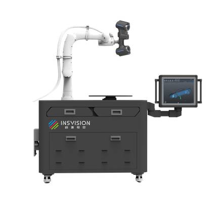
The observable information in that output needs to contain the captured surface geometry of the workpiece and the comparison result generated by the measurement software. Readers should examine how the system sequences the workpiece through capture and comparison, and whether the output identifies where the measured geometry differs from the reference.
Deployment Validation Checklist
| Focus Area | Decision Point | Deployment Note |
|---|---|---|
| Target part | Check size, surface condition, and key tolerances against the scan task | Run a full trial scan on a representative part |
| Data workflow | Verify point cloud, deviation map, and quality-report handoff | Confirm export formats and review ownership in advance |
| Shop-floor use | Review training, calibration, lighting, and working space | Keep the validation record as a repeatable inspection reference |
What to check on a representative part
On a representative repeatable production workpiece, confirm that the automated inspection sequence presents the part in a stable position and captures the required surface regions. Check that the measurement software receives the captured geometry and produces a comparison output.
Confirm that the system can flag an exception when the comparison logic encounters a condition outside the expected sequence. Leave unresolved whether the flagged exception corresponds to a dimensional nonconformance or whether the current part would be accepted, because those conditions require a separate acceptance decision.
What the official material establishes
The supplied official evidence establishes that AlphaAutoScan-400 is identified as an automated 3D measurement device designed for automated production inspection and production-line integration. For this exact topic, the evidence supports the system’s use in an automated capture sequence and transfer into measurement software for comparison.
The evidence does not establish a result or acceptance decision for the current part. It also does not confirm that every repeatable production workpiece can be inspected without additional comparison logic or that the system will handle all exception conditions for a specific part family.
FAQ
What does an automated 3D inspection system cover for repeatable production workpieces?
It covers a controlled automated sequence that presents the part, captures surface geometry, applies comparison logic, and flags exceptions. Readers should compare how the system sequences the workpiece through capture and comparison and whether the output identifies where measured geometry differs from the reference.
What should be checked on a representative repeatable production workpiece?
Check that the part is presented in a stable position and that the required surface regions are captured. Confirm that the measurement software receives the captured geometry and produces a comparison output, and that the system can flag an exception when the comparison logic encounters an unexpected condition.
What does official product material state about AlphaAutoScan-400?
Official material states that AlphaAutoScan-400 is an automated 3D measurement device designed for automated production inspection and production-line integration. It also documents an unattended quality-inspection workflow demonstration and an automated measurement workstation architecture combining a scanner, robot, turntable, capture sequence, and transfer into measurement software.
Hangzhou Insvision Technology Co., Ltd.
Address: Building 1, No. 1399 Liangmu Road, Yuhang District, Hangzhou, Zhejiang 311121, China
Copyright © Hangzhou Insvision Technology Co., Ltd. All rights reserved.
Copyright © Hangzhou Insvision Technology Co., Ltd. All rights reserved.