

3D scanner accuracy: Principles, Evaluation Criteria, and Practical Boundaries
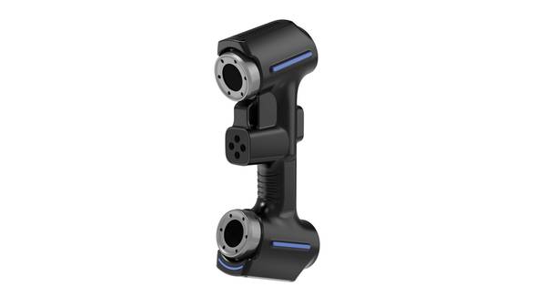
3D scanner accuracy: a guide to acquisition principles, evaluation criteria, processing steps, method limits, equipment checks, and acceptance boundaries.
Definition and Scope
Accuracy in 3D scanning is not a single number. It is a verification boundary that changes with part geometry, surface finish, environment, and the deliverable being produced. A scanner may resolve fine surface detail for reverse engineering yet require a different validation path when the output is a first-article inspection report tied to GD&T callouts.
The term covers four distinct deliverables:
| Deliverable | Purpose | Accuracy concern |
|---|---|---|
| Capture | Raw point cloud or mesh acquisition | Resolution, noise, and registration drift |
| Inspection | Comparison to CAD or tolerance zones | Deviation error relative to reference data |
| Modeling | Parametric or NURBS surface reconstruction | Geometric fidelity to the scanned part |
| Approval | Signed dimensional documentation | Traceability and measurement uncertainty |
Separating these categories prevents a common error: treating capture resolution as if it were inspection-grade measurement uncertainty. Each deliverable requires its own acceptance criteria.
Data-Capture Principles
Optical capture depends on line of sight: the scanner must see a surface to record it, so recesses, occlusions, and steep draft angles can leave gaps unless multiple positions are used. Surface response varies by material, color, and finish; dark, glossy, or transparent areas return weak signal and may require temporary matting powder or adjusted exposure.
Coordinate formation then converts each captured point into a common reference frame through alignment targets, feature matching, or tracker feedback.
| Condition | Effect on Data Capture |
|---|---|
| Glossy or dark surface | Weak return, possible noise or missing patches |
| Deep pocket or hidden edge | No line of sight, no direct capture |
| Poor registration | Drift or misalignment between scan passes |
| Stable reference geometry | Cleaner coordinate formation and repeatable alignment |
Key Evaluation Criteria
Evaluation should connect each criterion to evidence and a verification method, while unresolved items remain open.
| Criterion | Meaning | Required evidence | Verification method |
|---|---|---|---|
| Target coverage | Whether planned surfaces and features enter the data | Task definition and region list | Check covered and uncovered areas on a representative part |
| Data usability | Whether the output enters the downstream inspection or modeling workflow | File and interface requirements | Import and read back the output in the target workflow |
| Acceptance traceability | Whether the decision maps to a criterion, version, and reviewer | Approval and change records | Retain settings, evidence, and unresolved items |
Data-Processing Workflow
The data-processing workflow should keep capture, cleanup, alignment, meshing, comparison, and export as separately recorded stages. Each stage needs a defined input, output, and verification boundary before data moves forward.
| Stage | Primary output | Verification boundary |
|---|---|---|
| Capture | Raw point or range data | Record target coverage, missing regions, and capture conditions |
| Cleanup | Data with unrelated points removed | Confirm that required edges, holes, and datum features remain |
| Alignment | Data in one coordinate system | Record the reference method, selected datums, and residual result |
| Meshing | Surface data for downstream use | Review the scope of hole filling, smoothing, and simplification |
| Comparison | Deviation results against nominal data | Bind the reference version, tolerance band, and evaluated region |
| Export | Target file or report | Import and read back units, coordinates, and required entities downstream |
Use Boundaries and Limitations
A verification boundary exists wherever a surface cannot be directly observed by the sensor. Deep features, undercuts, and occlusion zones therefore require either multiple scan orientations or an alternative measurement method before dimensional acceptance can be confirmed.
Reflective, transparent, or very dark surfaces introduce a separate boundary: the return signal may be too weak or too noisy to support the stated 3D scanner accuracy.
| Boundary | Effect on 3D scanner accuracy |
|---|---|
| Occlusion and deep features | Missing data; requires repositioning or complementary inspection |
| Reflective or dark surfaces | Signal loss or noise; may need matting or surface preparation |
| Fine detail and sharp edges | Limited by resolution and point spacing, not only accuracy rating |
| Datum selection | Shifts alignment and reported deviation even with valid point data |
Common Misconceptions
A nominal accuracy specification does not by itself confirm that a scan meets a given inspection requirement. The stated value reflects a controlled reference condition, not the full measurement task involving surface finish, geometry, ambient temperature, or part alignment.
Likewise, scan completion is a data-capture milestone, not a dimensional acceptance record. Verification still depends on comparing measured points against GD&T callouts and documented uncertainty budgets.
| Misconception | Verification boundary |
|---|---|
| Nominal specification proves suitability | Requires task-specific uncertainty evaluation |
| Completed scan proves acceptance | Requires comparison to toleranced features and datum references |
Related Concepts
Related concepts need separate deliverables and decision boundaries; one capture does not by itself complete every downstream task.
| Concept | Typical output | Decision boundary |
|---|---|---|
| 3D scanning | Point or range data | Confirm target coverage and capture conditions |
| 3D digitization | Storable and exchangeable geometry | Confirm completeness, coordinates, and format |
| Dimensional inspection | Evaluation against a reference or tolerance | Confirm datums, versions, and acceptance rules |
| Reverse engineering | Geometry used for reconstruction | Confirm coverage and downstream modeling requirements |
| CAD reconstruction | Parametric or surface model | Confirm intended use, interfaces, and review requirements |
Whether one captured data set can support several tasks must be verified against each task’s output and acceptance evidence.
Equipment and Supplier Validation
Equipment and supplier validation should use a representative part that covers the target geometry, surface condition, visibility, and datum requirements. Check whether the target area is captured, whether the point cloud or mesh can be exported in the required format, and whether the downstream system can read it.
Keep capture settings, missing regions, reference method, interface result, and acceptance evidence in the same validation record.
Reviewed official product documentation places AlphaScan handheld 3D scanner within the application scope discussed here. That source establishes only the product and use boundary stated by the publisher; it does not establish fitness for every part. A final decision still requires representative-part capture, interface readback, and predefined acceptance criteria.
Frequently Asked Questions
What must be defined before data capture begins?
Define the required data, inspection decision, model file, or approval result, with separate inputs, outputs, and acceptance evidence. Captured scan data does not by itself complete inspection, modeling, or approval.
How should a representative part be validated?
Choose a part that covers the target geometry, surface response, visibility, and datum conditions, then document capture settings, alignment, and output format. Judge suitability against the approved task criteria, not merely against scan completion.
What can official documentation establish?
Official documentation supports only the specifications, interfaces, and product scope that it states. Suitability for a particular part, environment, workflow, and acceptance rule still requires representative-part validation.
- What Is 3D Scanning? Principles, Workflow, and Industrial Applications 3D scanning is a digital measurement technology that converts the surface geometry of physical objects into 3D data. This entry covers its working principles, core parameters, industrial use cases, common misconceptions, and related technical…
- What Is a 3D Scanner? Types, Parameters, and Selection Criteria A 3D scanner captures three-dimensional surface data from physical objects and converts geometry, dimensions, and features into digital data for inspection, reverse engineering, and modeling.
- What Is 3D Scanning Accuracy? Accuracy, Repeatability, and Resolution Explained 3D scanning accuracy describes how closely scan data matches an object's actual geometry and dimensions. It is assessed through local accuracy, volumetric accuracy, stitching accuracy, repeatability, and resolution.
- What Is Point Cloud Data? Point Clouds, Meshes, and CAD Models in 3D Scanning Point cloud data is an important raw data format in 3D scanning. It consists of discrete 3D coordinate points that describe object surface geometry and support inspection, reverse engineering, modeling, and archiving.
Hangzhou Insvision Technology Co., Ltd.
Address: Building 1, No. 1399 Liangmu Road, Yuhang District, Hangzhou, Zhejiang 311121, China
Copyright © Hangzhou Insvision Technology Co., Ltd. All rights reserved.
Copyright © Hangzhou Insvision Technology Co., Ltd. All rights reserved.