

Key Differences Between 2D Imaging and 3D Scanning for 3D Scanner Sale Research
This article explains 3d scanner sale, including part conditions, scanning workflow, data review, reporting, product fit, and practical sample-validation criteria.
Core Definitions of 2D Imaging and 3D Scanning
On a typical production floor, the first-article inspection process often starts with a camera. An engineer snaps a photo of a machined bracket, uploads it to the quality report, and moves on. The image shows surface scratches, visible edge breaks, and general cosmetic condition. What it does not show is whether the hole-to-hole spacing drifted out of tolerance or whether the machined face is flat within 0.05 mm.
Common Questions
What should teams check when evaluating Core Definitions of 2D Imaging and 3D Scanning?
On a typical production floor, the first-article inspection process often starts with a camera.
Deployment Validation Checklist
| Focus Area | Decision Point | Deployment Note |
|---|---|---|
| Target part | Check size, surface condition, and key tolerances against the scan task | Run a full trial scan on a representative part |
| Data workflow | Verify point cloud, deviation map, and quality-report handoff | Confirm export formats and review ownership in advance |
| Shop-floor use | Review training, calibration, lighting, and working space | Keep the validation record as a repeatable inspection reference |
What should teams check when evaluating Working Principles and Common Technology Categories?
What are you actually measuring when you choose a 2D camera over a 3D scanner?
What should teams check when evaluating Application Boundaries and Use Case Alignment?
The key takeaway is straightforward: 2D imaging and 3D scanning solve different measurement problems, and neither is a universal replacement for the other.
That limitation sits at the core of the difference between 2D imaging and 3D scanning.
2D imaging captures flat, pixel-based visual data. The camera records light intensity and color across a plane, but it has no inherent depth information and no spatial coordinate system tied to the object’s real geometry. A photograph can document what a part looks like. It cannot document what the part measures.
3D scanning operates differently. The scanner collects three-dimensional coordinate data across the object’s entire visible surface. Each captured point carries X, Y, and Z values relative to a defined reference frame. The result is a digital representation of physical geometry — a point cloud or mesh that can be compared against CAD models, checked for GD&T callouts, or used for reverse engineering.
For procurement professionals and quality managers researching a 3D scanner sale, this distinction matters before any budget discussion begins. A 2D system may be sufficient for cosmetic documentation or barcode verification. It will not support dimensional inspection, profile analysis, or surface deviation mapping. Selecting the wrong tool because the terminology was unclear leads to equipment that sits unused on a shelf.
The INSVISION product line, for example, includes systems designed specifically for coordinate-based measurement rather than image capture. Understanding what 3D scanning is — and what it is not — is the first filter in a technically sound purchase decision.
Working Principles and Common Technology Categories
What are you actually measuring when you choose a 2D camera over a 3D scanner? The answer comes down to the physics of how each device captures data, and that difference drives everything from inspection speed to file size to whether a system will even work in your plant environment.
2D imaging relies on either a charge-coupled device (CCD) or complementary metal-oxide-semiconductor (CMOS) sensor. Both work on the same basic principle: light reflects off a surface, hits the sensor, and each pixel records an intensity value. That produces a flat pixel array with no depth information.
Area scan cameras capture the full field of view in one exposure, which suits part presence checks, label verification, and general machine vision tasks. Line scan cameras build an image row by row as material moves past the sensor, making them the standard choice for web inspection, continuous extrusion lines, and cylindrical surface unwrapping.
The output is always 2D: length and width, with contrast revealing edges, text, or surface defects.
3D scanning adds the third axis by calculating depth. Laser triangulation projects a laser line onto a surface and uses a known camera angle to measure how the line deforms across geometry. Structured light projection replaces the single line with a pattern, often a series of fringes or grids, and analyzes distortion across the entire field at once.
Photogrammetry takes multiple 2D images from different positions and computes depth through parallax and feature matching. Each method has different strengths for surface finish, ambient light tolerance, and accuracy limits.
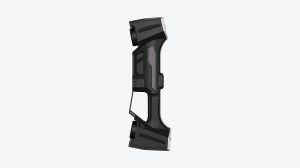
Form factor matters just as much as the underlying technology when you start narrowing down a 3D scanner sale. Handheld scanners give you flexibility for large or awkward parts, but they demand operator skill and a stable tracking reference. Fixed scanners, typically mounted on a stand or robot, deliver repeatable measurements for inline or near-line inspection where the part comes to the scanner.
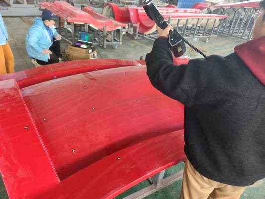
Large-format systems, often built around structured light or photogrammetry, handle automotive body panels, aircraft skins, and other meter-scale surfaces. The form factor decision should come before you compare accuracy specs, because a scanner that is too heavy to hold or too slow to integrate will fail in the field regardless of its nominal precision.
A practical note for quality managers: do not assume higher resolution solves every problem. A 2D camera with a 5-megapixel sensor can spot a missing fastener faster than any 3D scanner, because it does not need to reconstruct geometry first. But when you need to verify a GD&T callout like profile tolerance or flatness, only spatial data will do.
INSVISION systems, for example, include fixed and handheld configurations aimed at different inspection workflows, so the evaluation starts with what you need to measure and where the part sits during measurement.
Application Boundaries and Use Case Alignment
The key takeaway is straightforward: 2D imaging and 3D scanning solve different measurement problems, and neither is a universal replacement for the other. Matching the technology to the task matters more than chasing the highest resolution or the fastest cycle time.
2D machine vision earns its place on high-speed, high-volume lines. Surface defect detection, barcode reading, label verification, and presence/absence checks all work well when the part is flat or has a uniform shape. A camera grabs a frame, software compares it against a reference, and the line keeps moving.
That speed is hard to beat when you need to inspect hundreds of parts per minute and the failure mode is visual, not dimensional.
3D scanning steps in when geometry is the question. Dimensional inspection against GD&T callouts, reverse engineering of legacy components, digital twin creation for Industry 4.0 initiatives, and fit or assembly validation for complex curved surfaces all require full point-cloud data, not a flat image.
For example, an aerospace MRO team checking a turbine blade profile or an automotive supplier validating a stamped panel against its CAD model cannot rely on 2D pixels alone. They need surface deviation maps and true 3D coordinates.
That level of accuracy is not a marketing number. It is the difference between a first-article inspection that passes and one that drifts out of tolerance.
In practice, modern quality control workflows often use both technologies in tandem. A 2D camera flags a barcode or confirms a component is present. A 3D scanner then measures the critical geometry. One triggers the other. That combination keeps cycle times manageable while still capturing the data quality that lean manufacturing and digital twin programs demand.
Industrial Scenario Comparisons Across Key Sectors
A common misconception among quality engineers is that 3D scanning is simply an expensive upgrade to machine vision. In practice, these are two distinct tools that solve different problems. The choice is not about which technology is superior, but about what data the inspection actually requires.
Automotive OEM
On a body-in-white line, cycle time is non-negotiable. A 2D camera system remains the standard for high-speed cosmetic screening. It catches paint defects, dings, and surface contamination on body panels in milliseconds, flagging anomalies before they move downstream. But when a closure panel sits proud of the fender by half a millimeter, a flat image cannot tell you why. That is where 3D scanning earns its place.
By capturing full panel geometry and comparing it against CAD nominal, engineers can isolate the root cause—whether it is hinge misalignment, stamping springback, or weld distortion. The 2D system answers “is this surface acceptable?” The 3D scanner answers “is this geometry correct?”
Aerospace MRO
In turbine blade overhaul, technicians rely on fluorescent penetrant inspection and 2D imaging for initial crack screening. It is fast and effective for finding surface-breaking defects on the leading edge or platform. The limitation appears when you need to quantify material loss. Airfoil wear is a three-dimensional problem.
A scanner captures the entire blade form and compares it to the OEM profile, giving you actual deviation values for chord width, thickness, and contour. This matters for repair conformity. You cannot weld and blend a blade back to spec without knowing exactly how much material is missing and where. Here, 2D finds the defect; 3D validates the repair.
Medical Device Manufacturing
For small orthopedic screws or surgical staples, a 2D vision system handles blemish detection and packaging verification at high volume. It confirms that a seal is intact or that a surface finish is free of scratches. The dimensional side is different. A custom implant—say, a patient-specific acetabular cup—must match the surgical plan within tight GD&T callouts.
3D scanning captures the organic, freeform surface and compares it to the design file. For surgical tools with complex mating features, a scanner verifies form, profile, and positional tolerances that a flat image simply cannot resolve.
Renewable Energy
Solar panel inspection relies heavily on electroluminescence imaging, a 2D technique that reveals micro-cracks in photovoltaic cells. It is non-destructive and fast enough for production line use. Wind turbine blades present a different challenge. A blade is a massive, curved composite structure. Damage assessment after a lightning strike or leading-edge erosion requires mapping the affected area in three dimensions.
Technicians use scanning to document the depth, width, and surface area of damage, then compare that data to the original blade geometry. This informs the repair scope and verifies that the finished patch matches the surrounding airfoil.
For large-scale components such as wind turbine blades or aerospace fuselage sections, a large-format handheld 3D scanner such as the INSVISION AlphaVista supports flexible on-site scanning without requiring part relocation or production line downtime.
The practical takeaway is that neither technology replaces the other. A well-equipped quality lab or production floor often uses both. The 2D system is the fast filter. The 3D scanner is the precision ruler. Knowing which problem you are solving determines which tool you pick up.
And when a 3D scanner sale inquiry comes in, the first question should always be about the data you need to collect, not the resolution of the sensor.
Common Misconceptions and Practical Evaluation Tips
A shift in manufacturing data capture is underway. More plants are moving from contact gauging to optical measurement, and that shift has created some confusion. Two misconceptions surface repeatedly during 3D scanner sale research, and both can lead teams toward expensive misalignment.
The first misconception is that 3D scanning eliminates the need for 2D imaging entirely. It does not. A 2D camera system captures edge profiles, surface contrast, and fast dimensional checks in a single plane. A 3D scanner reconstructs full surface geometry. They answer different questions.
In practice, many aerospace MRO and automotive first-article inspection workflows still pair a 2D image for quick verification with a 3D scan for GD&T evaluation of form, profile, or runout tolerance. One is not a replacement for the other. Smart teams integrate both.
The second misconception is that all 3D scanners perform equally across part types. That assumption falls apart quickly on a shop floor. A scanner configured for large sheet metal panels will not give the same results on small medical device components. Scan area, working distance, accuracy, and form factor all vary by design.
INSVISION equipment, for example, includes systems with distinct scanning areas and depth-of-field specifications to match different inspection envelopes. The right tool depends on your part size, material finish, and whether you measure in a lab or next to a production line.
Practical tip: during any 3D scanner sale evaluation, bring your own parts. Test against known GD&T callouts. Validate repeatability on the surfaces you actually inspect, not on a vendor demo block. Throughput matters too. A scanner that needs ten minutes per part may be fine for first-article work and useless for inline SPC. Match the tool to the task, not to the brochure.
Understanding the core differences between 2D imaging and 3D scanning gives you a solid, objective foundation. That clarity helps you select the right inspection tool for your manufacturing quality and efficiency goals, without falling for myths that sound reasonable but cost real money.
- What Is 3D Scanning? Principles, Workflow, and Industrial Applications 3D scanning is a digital measurement technology that converts the surface geometry of physical objects into 3D data. This entry covers its working principles, core parameters, industrial use cases, common misconceptions, and related technical…
- What Is a 3D Scanner? Types, Parameters, and Selection Criteria A 3D scanner captures three-dimensional surface data from physical objects and converts geometry, dimensions, and features into digital data for inspection, reverse engineering, and modeling.
- What Is 3D Scanning Accuracy? Accuracy, Repeatability, and Resolution Explained 3D scanning accuracy describes how closely scan data matches an object's actual geometry and dimensions. It is assessed through local accuracy, volumetric accuracy, stitching accuracy, repeatability, and resolution.
- What Is Point Cloud Data? Point Clouds, Meshes, and CAD Models in 3D Scanning Point cloud data is an important raw data format in 3D scanning. It consists of discrete 3D coordinate points that describe object surface geometry and support inspection, reverse engineering, modeling, and archiving.
Hangzhou Insvision Technology Co., Ltd.
Address: Building 1, No. 1399 Liangmu Road, Yuhang District, Hangzhou, Zhejiang 311121, China
Copyright © Hangzhou Insvision Technology Co., Ltd. All rights reserved.
Copyright © Hangzhou Insvision Technology Co., Ltd. All rights reserved.