

3D Scan Reflective Surfaces: Shop Floor to Quality Approval Workflow
Streamline inspection of polished or mirror-finish parts. Learn a repeatable 3D scan reflective surfaces workflow that reduces bottlenecks.
Shop-Floor Quality Bottlenecks for Reflective Component Inspection
Walk through any machining cell producing polished stainless steel implants, chrome-plated hydraulic rods, or milled aerospace tooling inserts and you will find the same quiet bottleneck. The part comes off the machine. The operator wipes it down, positions it on a surface plate, and starts pulling manual measurements with calipers, micrometers, or a height gage. On a matte aluminum bracket, that works.
On a mirror-finish surface, every light source becomes a problem. The CMM stylus skates. The optical comparator washes out. The operator tilts the part, shades it with a hand, repositions the fixture, and calls a supervisor when the repeatability does not look right.
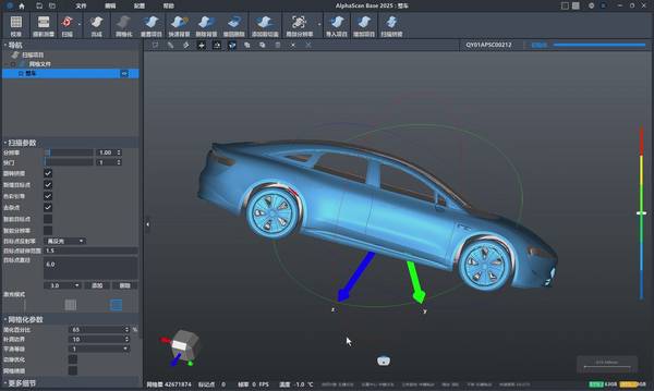
Deployment Validation Checklist
| Focus Area | Decision Point | Deployment Note |
|---|---|---|
| Target part | Check size, surface condition, and key tolerances against the scan task | Run a full trial scan on a representative part |
| Data workflow | Verify point cloud, deviation map, and quality-report handoff | Confirm export formats and review ownership in advance |
| Shop-floor use | Review training, calibration, lighting, and working space | Keep the validation record as a repeatable inspection reference |
Term Notes
Walk through any machining cell producing polished stainless steel implants, chrome-plated hydraulic rods, or milled…
A reflective part hits the inspection cell and the clock starts.
On-Station Scan Path Execution With Real-Time Quality…The real value of on-station scanning shows up when quality engineers and line operators stop working in sequence and start…
Post-Scan Processing and Cross-Functional Deviation…Are you still routing reflective-part inspection data through three different file formats before engineering even sees it?
From a lean perspective, this is overprocessing in its purest form. The same features get measured two or three times because the first reading is suspect. Waiting time piles up between machining, cleaning, inspection, and the quality handoff.
A first-article inspection on a reflective powertrain component can stretch days, not because the part is complex, but because the measurement process fights the surface finish at every step. When a defect is finally confirmed, the batch has already moved forward. Rework, scrap, and the paperwork follow.
Traceability makes the problem worse under ISO 9001 or AS9100. If the inspection record is a handwritten form or a spreadsheet screenshot, the auditor will ask how the operator verified a radius on a polished surface. The answer often involves tribal knowledge and a fixture that only one technician understands. That is a compliance risk and a training burden.
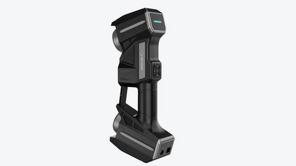
INSVISION addresses this with industrial 3D scanning built for reflective surfaces. The industrial 3D scanner handheld scanner captures geometry without relying on the part finish to cooperate.
For automated inspection of larger or rotated components, the industrial 3D scanner adds a turntable workflow with a 50 kg load capacity, so a polished tooling insert or implant tray can be scanned without manual repositioning between every view. The scanner outputs STL or PLY data that quality teams can compare against CAD, run GD&T evaluations on, or archive with the job record.
That shifts the bottleneck from measurement guesswork to a repeatable digital workflow, and it gives production and quality a shared dataset instead of a disputed reading.
Pre-Scan Preparation Aligned With Cross-Team Quality SOPs
A reflective part hits the inspection cell and the clock starts. The production technician knows the scanner will struggle if the surface has residual coolant, fingerprint contamination, or uneven oxide layers. The quality engineer knows the scan only matters if the right features are captured and the equipment was verified before the first part went on the fixture.
When these two roles work from separate assumptions, the result is predictable: a scan that looks complete but fails downstream comparison, or a re-scan that burns thirty minutes and disrupts the shift.
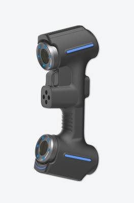
Aligned pre-scan preparation removes that variance. It defines what happens before the scanner runs, who does it, and what condition the part and equipment must be in. For reflective surfaces, this discipline matters more than for matte or painted components because small surface inconsistencies directly affect data quality.
The production technician’s responsibility starts with staging. The part should be positioned in the same orientation every time, using the same fixture or support points specified in the work instruction. If the component has machined surfaces, the technician follows the quality guideline for surface conditioning. That typically means a clean, dry surface free of oil, coolant residue, or loose debris.
Some facilities use a controlled wipe procedure with approved solvents. Others require the part to reach ambient temperature before scanning, since thermal expansion or condensation on a cold reflective surface can introduce measurement noise. The technician also confirms that the scan area is clear of stray light sources, vibration, or moving equipment that could affect data capture.
The quality engineer’s role runs parallel, not sequential. Before production starts, the engineer verifies calibration using the reference artifact or procedure defined in the quality SOP. This is not a formality. Reflective surface scanning is sensitive to equipment drift, and a scanner that passed calibration on the previous shift is not automatically ready on this one.
The engineer also marks critical inspection features before the scan begins. These are the surfaces, bores, edges, or GD&T callouts that need to be captured and compared. Marking them in advance ensures the scan path covers them and the downstream analysis focuses on the dimensions that actually drive part acceptance.
When these two roles work from the same pre-scan checklist, the scan itself becomes a routine operation rather than a troubleshooting event. Re-scans drop because the part was staged correctly and the equipment was verified. Shift-to-shift consistency improves because the procedure does not depend on one experienced operator’s memory.
A new technician can follow the staging steps, and a new quality engineer can follow the calibration and marking steps without extensive retraining.
INSVISION industrial 3D scanning solutions support this workflow for reflective components. The equipment is designed to operate within shop-floor inspection cells where production technicians and quality engineers share the same station. The software interface allows the quality engineer to define inspection features and review scan data without rebuilding the scan setup for every part number.
That means the pre-scan SOP stays stable across shifts, and the routine tasks do not require a scanning specialist to be present for every cycle.
The operational value is straightforward. Aligned pre-scan preparation reduces the number of scans that fail verification, shortens the time between part arrival and usable inspection data, and lowers the labor cost associated with rework and exception review.
It also creates a traceable record: the technician logged the staging and surface condition, the engineer logged the calibration check, and the scan data carries that context forward. When a customer audit asks how a reflective part was measured, the answer is documented, not reconstructed from memory.
For facilities handling reflective parts across multiple inspection stations, this cross-team alignment is the difference between a scanning process that occasionally works and one that produces consistent results every shift. The SOP does not need to be long. It needs to be specific, assigned, and followed.
On-Station Scan Path Execution With Real-Time Quality Checks
The real value of on-station scanning shows up when quality engineers and line operators stop working in sequence and start working in parallel. Before a part ever reaches the inspection station, engineering defines which reflective features matter most: sealing surfaces, machined bores, datum faces. These high-tolerance areas get flagged for priority coverage in the scan path.
The operator doesn’t need to interpret GD&T callouts or guess where the scanner might struggle with a shiny surface. The path is already built around those regions.
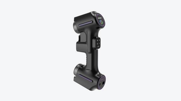
During execution, in-capture validation confirms coverage while the scan is still running. Operators see immediately whether a bore was fully captured or a flange edge needs another pass. That check happens at the station, not later in a metrology lab. When the part leaves the station, the data is already usable.
This removes a common bottleneck. Factories no longer wait for a specialized metrology technician to review scans, flag missing patches, and send the part back for rework. Routine inspection stays on the line. Engineers stay focused on exceptions and process improvements.
INSVISION 3D scanning solutions support this workflow for reflective parts, helping teams complete full surface capture without breaking production takt time.
Post-Scan Processing and Cross-Functional Deviation Review
Are you still routing reflective-part inspection data through three different file formats before engineering even sees it? That handoff friction is where a lot of root-cause time disappears. Post-scan processing for reflective surfaces works best when the workflow is treated as a structured data path, not a series of software exports.
Start with point cloud cleanup. Reflective aerospace and automotive parts often produce noise around edges, fastener holes, and machined transitions. The operator removes outliers, aligns scan passes, and decimates the mesh only as much as needed for downstream CAD comparison. Over-cleaning hides real deviation; under-cleaning creates false callouts.
Once the mesh is stable, the scan is aligned to nominal CAD using datum features that match the drawing’s GD&T reference frame. That alignment choice matters more than most teams admit. If quality, process engineering, and production supervision don’t agree on the datum scheme before scanning, the deviation map will trigger the wrong conversations later.
The deviation mapping step is where cross-functional review actually begins. Color-coded variance plots let a quality inspector see form issues while a process engineer reads the same map for tool wear or clamping distortion. Standardizing this output for reflective surfaces shortens defect diagnosis because everyone reviews the same color scale, the same tolerance bands, and the same pass/fail thresholds.
There is less back-and-forth about whether a red zone is real or a scanning artifact. For reflective materials, INSVISION 3D scanning solutions support core inspection and CAD comparison workflows, so the deviation data feeds directly into the review cycle rather than waiting on a separate metrology report.
Traceability closes the loop. Each scan file linked to a work order, operator ID, and machine cell gives aerospace MRO and automotive OEM programs the audit trail they require. When a defect trend appears across a batch, the team can pull deviation maps by shift, fixture, or tool revision. That linkage reduces the time spent hunting for context during corrective action.
Fewer unresolved debates, faster containment, less rework volume. Structured handoff between quality, engineering, and production is not a software feature. It is the part of the process that turns scan data into a decision.
Output Compatibility for Internal and Customer Quality Reviews
The shift toward digital inspection records has changed how Western manufacturers handle first-article approval, supplier qualification, and internal quality gates. A few years ago, scan data from reflective surfaces often lived in a separate software silo.
The scan itself might be accurate, but getting that data into PolyWorks, Geomagic, GOM Inspect, or a customer’s PLM environment meant manual export, reformatting, or even rescanning. That friction added hours to approval cycles and created version-control risk when multiple teams touched the same file.
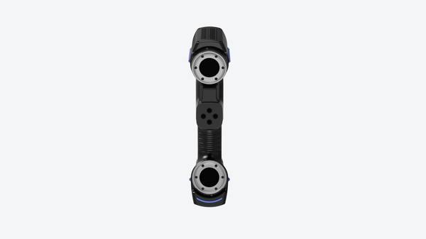
INSVISION scanning solutions generate output formats such as STL, PLY, and TXT, which align with the inspection and design tools most Western medical device and energy sector teams already use. That matters operationally. A quality engineer can bring reflective surface scan data into an existing QMS workflow without rebuilding the pipeline.
MES integration is also supported on the industrial 3D scanner, which allows interaction with third-party system databases, so inspection results can move into production records without a separate manual entry step.
For customer-facing quality reviews, the practical benefit is faster, cleaner handoff. When a supplier submits scan data that drops into the customer’s existing inspection software, the review team spends less time on file conversion and more time evaluating actual deviation maps and GD&T callouts.
That shortens the loop between dimensional verification and disposition, whether the part is a polished orthopedic implant component or a reflective turbine blade surface. Over multiple projects, that reduction in formatting labor and rework compounds into measurable delivery cadence improvement, not just a one-time time saving.
Reinspection Triggers and Standardized Follow-Up Protocols
Plain text, no markdown. Here is the section:
With more plants moving toward automated dimensional verification for high-gloss and polished components, the conversation has shifted from “can we scan it” to “how do we prove we got it right the second time.” Reflective surfaces are unforgiving during 3D scan workflows. A mirror-like turbine blade or a chrome-plated hydraulic fitting can look clean on screen while hiding subtle data dropout.
That reality forces quality teams to stop treating reinspection as an ad hoc event. It needs triggers, thresholds, and a repeatable path back to the original scan setup.
Three triggers should drive a follow-up scan on a reflective part. The first is deviation threshold flags during initial analysis. If the comparison against CAD shows localized spikes near the edge of the tolerance band, or if surface noise clusters in areas where the scanner had to fight glare, that is a signal to reinspect before release. The second trigger is customer-requested verification.
This often comes after a first-article submission or when the customer’s incoming QC sees variation that does not match the supplier’s report. The third trigger is periodic process validation. Even when no individual part fails, scheduled reinspection of a retained sample or a production part at defined intervals confirms the measurement system has not drifted.
The value of standardized reinspection lies in documented scan parameters and comparison criteria. A follow-up scan is only useful if it uses the same scanning distance, angle strategy, exposure settings, and alignment references as the original inspection. Without that, the second dataset cannot be compared to the first.
Teams running INSVISION industrial 3D scanners for reflective surface inspection should treat scan parameters as part of the quality record, not as operator preferences. When the turntable position, scan path, and post-processing steps are fixed, the initial scan and the follow-up scan become directly comparable.
That consistency removes the classic back-and-forth where a customer sees one deviation map, the supplier sees another, and neither side trusts the data.
From a lean manufacturing standpoint, structured reinspection protocols do more than settle disputes. They build long-term quality data sets. Each follow-up scan adds a controlled data point to the part history. Over time, quality engineers can see whether deviation patterns on reflective features are stable, improving, or slowly shifting with tool wear or fixture relaxation.
That trend visibility supports continuous improvement initiatives without requiring a separate data collection project. It also strengthens customer trust because the supplier can show not just a final pass/fail result, but a documented trail of how the measurement was taken, what triggered the reinspection, and how the two datasets compared.
The operational payoff is straightforward. Fewer ambiguous measurements mean less rework, fewer customer returns, and shorter release cycles for parts that are already difficult to measure. Reflective surfaces will always be challenging, but a clear reinspection protocol turns that challenge into a controlled process instead of a recurring argument.
Hangzhou Insvision Technology Co., Ltd.
Address: Building 1, No. 1399 Liangmu Road, Yuhang District, Hangzhou, Zhejiang 311121, China
Copyright © Hangzhou Insvision Technology Co., Ltd. All rights reserved.
Copyright © Hangzhou Insvision Technology Co., Ltd. All rights reserved.