

How to Validate a 3D Laser Scanner for Precision Manufacturing Inspection
Learn which 3D laser scanner capabilities to test for deep holes, reflective surfaces, and FAI workflows before you commit to one.
Your Evaluation Starting Point: Align Scanner Capabilities to Core Inspection Tasks
Quality leads and process engineers evaluating a 3D laser scanner for the production floor often start with the wrong document. The spec sheet’s single-number volumetric accuracy looks decisive, but it rarely predicts how the system will handle your actual parts.
A scanner that nails a flat prismatic block may struggle with the deep bore diameters in an aerospace MRO fuel manifold or the fine edge geometry on a medical device housing.
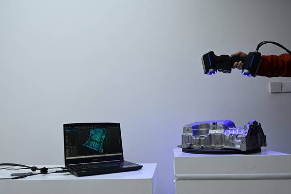
Deployment Validation Checklist
| Focus Area | Decision Point | Deployment Note |
|---|---|---|
| Target part | Check size, surface condition, and key tolerances against the scan task | Run a full trial scan on a representative part |
| Data workflow | Verify point cloud, deviation map, and quality-report handoff | Confirm export formats and review ownership in advance |
| Shop-floor use | Review training, calibration, lighting, and working space | Keep the validation record as a repeatable inspection reference |
Practical Workflow
- Your Evaluation Starting Point: Align Scanner Capabilitie… — Quality leads and process engineers evaluating a 3D laser scanner for the production floor often start with the wrong document.
- Common Risks of Misaligned 3D Laser Scanner Deployments — What is the real cost of choosing a 3D laser scanner that looks right on a datasheet but falls short on the shop floor?
- Non-Negotiable Verification Criteria for Industrial 3D La… — How do you trust that a 3D laser scanner will actually perform on your production floor, not just in a supplier’s demo room?
- How INSVISION 3D Laser Scanners Align With Industrial Ins… — Quality leads evaluating a 3D laser scanner for production inspection usually start with the wrong question.
Before comparing accuracy claims, define the four tasks that drive your inspection load: first article inspection against AS9102, in-process dimensional checks on machined features, deep hole measurement where line-of-sight fails, and final part validation for release. Each task stresses a different scanner characteristic. FAI rewards dense point coverage and clean GD&T extraction.
Deep hole work depends on a single narrow laser line reaching where multi-line patterns cannot. Final validation requires repeatable setup and stable reference alignment.
A neutral verification checklist should map these tasks to observable performance, not marketing language. Ask suppliers to scan a representative part with the same fixtures, surface finish, and cycle-time constraints you face. Confirm what the system reports under ISO 10360 conditions and what it produces in your environment. That evidence closes the gap between advertised accuracy and inspection capability.
Common Risks of Misaligned 3D Laser Scanner Deployments
What is the real cost of choosing a 3D laser scanner that looks right on a datasheet but falls short on the shop floor? For quality leads evaluating inspection tools, the answer usually shows up weeks later, in rework hours, line stoppages, or compliance headaches. The problem is rarely the scanner’s published accuracy.
It’s the mismatch between what the spec sheet claims and what the actual part geometry, production cadence, and site safety rules demand.
Misaligned deployments create predictable pain points. Four stand out in industrial practice.
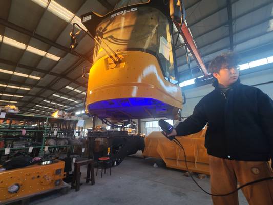
First, there’s the rework trap. A scanner that cannot reliably capture deep holes, undercuts, or fine surface details will force inspectors back to slow contact CMM probing. On first-article inspection work, where GD&T callouts include tight positional tolerances on recessed features, this fallback erases the time savings that justified the scanner purchase.
The scan file looks complete until the comparison report flags missing data, and then someone has to re-fixture the part anyway.
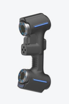
Second, scan speed becomes a bottleneck. High-volume in-process inspection lines cannot wait for a slow capture cycle. If the scanner’s effective throughput lags behind takt time, parts queue at the inspection station. The scanner becomes the constraint, not the measurement tool.
Third, laser class creates deployment friction. Non-eye-safe laser classes force restricted work zones or require personal protective equipment. In shared production areas where operators, forklifts, and assembly staff move through the same space, that restriction complicates layout and slows every inspection routine. An eye-safe Class II scanner avoids this entirely.
Fourth, data integration friction is easy to underestimate. If scan data doesn’t flow cleanly into existing CAD comparison or quality management software, operators spend hours manually aligning meshes, converting formats, or rebuilding reports. That manual step adds labor cost and introduces transcription risk.
INSVISION industrial 3D scanners address these risks through task-fit design. For deep hole and fine feature capture, a single blue laser line scanning mode reaches areas that multi-line modes miss. For high-speed inspection, a 50 blue laser line mode on suitable configurations supports faster surface coverage without forcing a separate tool.
For shared production areas, Class II eye-safe laser operation removes the need for restricted zones in many layouts. And for software workflow, scan outputs are built to feed standard CAD comparison and quality management pipelines, reducing manual data processing.
The evaluation question isn’t whether a 3D laser scanner can scan. It’s whether the scanner matches the specific feature set, inspection cadence, safety environment, and data workflow of the line where it will run. Spec sheets won’t answer that. A validation part, scanned under real site conditions, will.
Non-Negotiable Verification Criteria for Industrial 3D Laser Scanners
How do you trust that a 3D laser scanner will actually perform on your production floor, not just in a supplier’s demo room? The answer is a task-first verification process, using your own parts and your own operators. Spec sheets can be misleading. A scanner that excels on a matte, grey casting may fall apart on an anodized aluminum bracket or a polished stainless steel medical component.
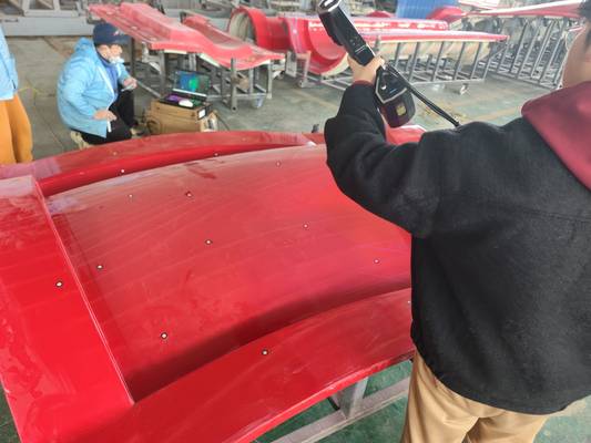
The evaluation starts with the workpiece, not the brochure. Bring in the parts that currently cause measurement bottlenecks: deep bores, thin-walled polymers, reflective coated surfaces. Have the supplier scan them without pre-treatment or special lighting. Watch how the scanner handles transitions between geometries. Does the operator need to switch modes manually, or does the scanner adapt?
This section outlines a four-point, non-negotiable checklist for testing any 3D laser scanner against your operational reality. Each criterion is paired with an on-site test method so that you can remove guesswork from the purchase decision.
How INSVISION 3D Laser Scanners Align With Industrial Inspection Requirements
Quality leads evaluating a 3D laser scanner for production inspection usually start with the wrong question. They ask whether a scanner is “accurate enough” before defining what the scanner must actually capture on a given part. That leads to buying equipment that works in a lab and stalls on the floor.
A better starting point is to break the decision into four verifiable criteria: feature access, deployment safety, software compatibility, and the ability to confirm all three with real parts before purchase.
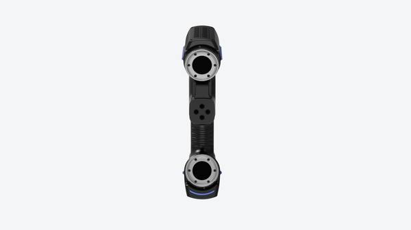
INSVISION industrial 3D laser scanners address these criteria through capabilities that can be tested directly during a no-obligation sample scan. The first criterion is feature access. Parts with deep holes, recessed pockets, or narrow slots often defeat scanners that only project wide multi-line patterns. INSVISION scanners include a single-line configuration for deep hole feature capture.
This matters in automotive valve bodies, aerospace brackets, and medical instrument housings where critical geometry sits below the surface. The same scanner can switch to multi-line configurations for high-precision scanning on sealing faces or high-speed scanning on larger castings and molded parts. That flexibility supports varied part inspection needs across a single production line without swapping equipment.
The second criterion is whether the scanner can operate in a shared production environment. INSVISION industrial scanners use a Class II eye-safe laser classification. This means the unit can be deployed near assembly stations, CMM benches, or manual inspection cells without dedicated restricted access zones. Engineers do not need to rope off an area or write new safety permits before running a first-article check.
For Western factories that run lean layouts and move inspection stations as production lines change, this is a practical requirement, not a convenience.
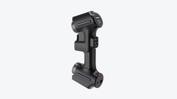
The third criterion is data flow. A scanner is only useful if its output moves into existing quality workflows. INSVISION scanners work with standard industrial metrology and CAD comparison software. Inspection teams can bring scan data into the same software they already use for dimensional reporting, GD&T evaluation, and first-article documentation.
Integration does not require a separate proprietary ecosystem or a new reporting format that quality engineers have to learn from scratch.
The fourth criterion is verification. Rather than relying on specification sheets, teams can send a representative part for a no-obligation sample scan. The evaluation should include a deep-hole feature, a multi-line scan on a critical surface, and a CAD comparison report. That test confirms whether the scanner captures the required geometry and whether the output fits existing quality management workflows.
INSVISION’s focus on industrial metrology means the product discussion stays on scan coverage, laser safety, and software compatibility, not on marketing language. For quality leads building an internal verification checklist, these three capabilities provide a concrete starting point. If the scanner passes those checks on real parts, it is probably a fit for the line.
If not, the limitation will show up during the sample scan, before a purchase decision is made.
Run a Low-Risk Validation Test to Confirm Performance Before Purchase
Quality engineers evaluating a 3D laser scanner rarely worry about whether the technology works in a demo room. The real question is whether it holds up on their own parts, under their own tolerances, and inside their existing inspection workflow. A structured validation test answers that question before capital approval moves forward.
The process starts with part selection. Send two or three representative production parts, not idealized samples. Include the features that actually cause trouble on the shop floor: deep hole geometries, tight-tolerance surfaces with GD&T callouts, and reflective or coated finishes that confuse optical systems. If the scanner struggles on these, you will see it quickly.
Next, cross-reference the scan data against existing CMM results for the same critical features. This is the evidence step. Compare deviations on diameter, position, profile, and runout. The scan data does not need to match CMM exactly, but it must fall within your internal quality acceptance limits. If the correlation is weak, dig into alignment strategy, scan density, or feature extraction settings before rejecting the tool.
Workflow integration matters as much as dimensional accuracy. Import the scan mesh into your existing quality software and generate a sample first-article inspection report. Check whether the data flows cleanly or requires manual rework. A scanner that produces accurate data but forces your team to rebuild every inspection routine will stall adoption.
Finally, put the unit in front of the operators who will use it daily. Watch them scan, align, and export. Note how long setup takes, whether the laser class requires additional safety controls, and how quickly a new user reaches repeatable results. Ease of use on day one predicts long-term utilization.
INSVISION supports sample testing for industrial prospects through this exact validation path. That approach lets quality leads and evaluators confirm fit before any financial commitment, reducing implementation risk on a tool that should integrate with the inspection process rather than sit on a shelf.
FAQs and Quick Reference Validation Checklist
FAQs and Quick Reference Validation Checklist
Before committing to any 3D laser scanner for precision manufacturing, most evaluators run into the same four questions. Here are direct answers tied to real inspection workflows.
Can a 3D laser scanner capture deep hole features with the same level of reliability as a contact CMM?
Not by default. Contact CMMs still hold an advantage in very deep, narrow bores where line-of-sight access is limited and probe deflection can be controlled. However, scanners with a dedicated deep hole scanning mode using a single blue laser line can reach into recessed features that multi-line modes miss.
The practical approach is to validate against a calibrated reference part with known bore depths and diameters, then compare scanner output to CMM baseline data before replacing any touch-probe routine.
What laser classification is required for unrestricted 3D laser scanner use on shared production floors?
Class II is the threshold for eye-safe operation without controlled-area restrictions. The industrial 3D scanner platform uses Class II eye-safe lasers, which means operators do not need laser safety enclosures or dedicated rooms under normal use. Some projector-based systems use Class 3R lasers below 5 mW, which are not safe for direct eye viewing and require signage or controlled access.
On a shared floor with pedestrian traffic, Class II simplifies deployment significantly.
How do I test 3D laser scanner performance on reflective metal or polymer parts?
Start with a representative sample set that includes polished aluminum, machined steel, and dark or translucent polymers. Run the scanner in its precision scanning mode, then compare point cloud density and surface noise in areas with high specular reflection. If the scanner struggles, adjust exposure settings or apply a thin developer spray.
The key metric is repeatability across five consecutive scans of the same surface, not just visual completeness of the mesh.
Can 3D laser scan data integrate with existing AS9102 FAI reporting workflows?
Yes, provided the scanner exports neutral formats such as STEP, IGES, or high-density point clouds that downstream inspection software can read. The typical workflow is scan-to-mesh, mesh-to-CAD comparison, then export deviation reports into the FAI documentation package. Confirm that your inspection software accepts the scanner’s native export format before finalizing a purchase decision.
Condensed 1-Page Validation Checklist
Use this as a takeaway reference when evaluating a 3D laser scanner for precision manufacturing.
Feature Verification Criteria
Deep Hole Access: Confirm a single-line scanning mode exists and test on a bore with a depth-to-diameter ratio above 3:1.
Laser Safety Class: Require Class II for unrestricted floor use; treat Class 3R as needing controlled access.
Reflective Surface Handling: Test on polished metal and dark polymer without spray, then with spray, and compare repeatability.
Data Export Compatibility: Verify neutral format export works with your FAI or SPC software without manual rework.
This checklist keeps the evaluation focused on measurable performance rather than supplier claims.
Hangzhou Insvision Technology Co., Ltd.
Address: Building 1, No. 1399 Liangmu Road, Yuhang District, Hangzhou, Zhejiang 311121, China
Copyright © Hangzhou Insvision Technology Co., Ltd. All rights reserved.
Copyright © Hangzhou Insvision Technology Co., Ltd. All rights reserved.