

Why Aerospace MRO Blade Inspection Is Hard Without a 3D Scanner
Discover why traditional tools fall short on turbine blade inspection and how a 3D scanner captures full worn profiles for faster MRO decisions.
The Core Inspection Scope for Aerospace MRO Turbine Blade Overhauls
Aerospace MRO turbine blade overhauls live and die by the accuracy of a handful of critical measurements. Leading edge erosion depth, trailing edge thinning, root form deviation, and composite repair mapping determine whether a blade goes back into service or gets scrapped. Get any of these wrong and the cost is not just a rejected part. It is an engine removal, a schedule slip, and a very unhappy operator.
Practical Workflow
- The Core Inspection Scope for Aerospace MRO Turbine Blade… — Aerospace MRO turbine blade overhauls live and die by the accuracy of a handful of critical measurements.
- On-Site and Part-Specific Constraints That Impact Measure… — Most inspection failures in aerospace MRO do not happen because a scanner lacks resolution on a calibration artifact.
- Common 3D Capture Risks That Derail MRO Inspection Workfl… — Are you losing more time reworking scan data than actually inspecting blades?
- How INSVISION 3D Scanners Align With MRO Inspec… — Many MRO teams assume a 3D scanner is only as useful as its nominal accuracy spec.
Traditional workflows make these checks slow. Calipers and height gauges cover only discrete points. Fixed CMMs need hard fixturing and full disassembly before a blade can even be touched. Free-form airfoil surfaces and blended repair zones sit outside what these tools can realistically capture. The result is long setup time, sparse data, and inspection reports that leave too much to interpretation.
A solution engineer walking into an MRO shop starts by looking at the actual blade population. Which parts come in with the worst erosion? Where do inspectors spend the most time fighting the equipment instead of measuring the part? What does the release paperwork actually require? The goal is not to replace every tool on the bench.
Deployment Validation Checklist
| Focus Area | Decision Point | Deployment Note |
|---|---|---|
| Target part | Check size, surface condition, and key tolerances against the scan task | Run a full trial scan on a representative part |
| Data workflow | Verify point cloud, deviation map, and quality-report handoff | Confirm export formats and review ownership in advance |
| Shop-floor use | Review training, calibration, lighting, and working space | Keep the validation record as a repeatable inspection reference |
It is to define where a 3D scanner removes the bottleneck without disrupting the flow around it.
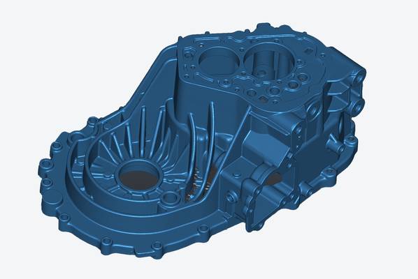
For these inspections, an INSVISION industrial 3D scanner changes the data density equation. Instead of twenty caliper points along a leading edge, the scanner captures the full worn profile. Instead of a CMM operator probing three points on a root form, the scanner delivers a dense point cloud that can be compared directly to the nominal CAD model.
The scan itself does not care whether the surface is a machined fir-tree root or a hand-blended composite patch. That matters in MRO, where no two incoming blades are exactly alike.
Deployment follows a practical sequence. First, the blade is staged in a stable position, often still mounted in a simple holding fixture. The scanner captures the airfoil, platform, and root in one or more passes. Alignment is done against reference geometry, not a fragile zero point. Areas with poor coverage or edge dropout trigger a targeted rescan rather than a full redo.
Validation happens before the blade leaves the bench: the software checks that the scan density is sufficient for every inspection callout and that the alignment residuals are within tolerance. Only then does the data move into the erosion, wear, or deviation analysis.
The operational value shows up in turnaround time and confidence. Shops that previously waited for CMM availability can run first-pass inspection at the bench. Areas that were never fully documented, like blended composite repairs, now have a complete digital record. When an engineer signs off a blade as serviceable, the scan data backs that decision.
For lean MRO environments chasing reduced turnaround time, that shift from sparse sampling to full-surface documentation is the difference between a known part and an assumed one.
On-Site and Part-Specific Constraints That Impact Measurement Reliability
Most inspection failures in aerospace MRO do not happen because a scanner lacks resolution on a calibration artifact. They happen on the shop floor, at the blade rack, under mixed lighting, with the clock running. A scanner that performs well in a lab can produce useless data when pointed at a turbine blade that has just come out of service.
The blade itself is the first problem. Free-form airfoil geometry is difficult enough, but the critical zones are usually the root and shroud. These areas contain undercuts, fillets, and transitions that are hard to reach with a fixed scanning path.
If the scanner cannot capture the full root form without repositioning the part multiple times, the resulting mesh will have gaps or interpolation errors exactly where stress concentrations matter most.
Surface condition is the second constraint. Blades returning from service often retain residual thermal barrier coating. That coating is not a clean, matte surface. It can be textured, semi-reflective, or partially spalled. Some areas absorb laser light unevenly. Others produce specular reflections that confuse the sensor.
A scanner that requires uniform surface preparation before every capture will not survive contact with a real overhaul schedule. The tool has to tolerate the surface as it arrives, not as a lab technician would prepare it.
Then there is the environment. Open MRO bays are not metrology rooms. Lighting changes throughout the day. Dust from grinding and blending operations drifts through the air. Temperature swings occur near open bay doors. Any 3D scanning solution proposed for this environment must be evaluated under those conditions, not in a controlled demonstration.
If the system needs blackout curtains or a dedicated enclosure, it adds setup time and disrupts the flow of parts through the cell.
Takt time is the constraint that overrides everything else. Overhaul turnaround targets leave limited minutes per blade for inspection. The scanner must capture enough data to validate geometry without requiring full disassembly of the rotor or stator assembly. In-situ inspection means working around adjacent blades, fixtures, and tooling. The scanner operator may have restricted access angles and limited clearance.
Every additional setup, recalibration, or rescan consumes time that the MRO provider does not have.
These constraints should not be treated as negotiable preferences. They are the conditions under which the measurement either works or fails. A valid evaluation process starts by mapping them explicitly: blade geometry with undercut features, residual coating variability, ambient light and dust, restricted access, and the takt time window.
Any 3D scanning solution under consideration must demonstrate that it can operate within all of these simultaneously. A scanner that satisfies only some of them will generate data that looks acceptable in review but cannot be trusted for disposition decisions.
INSVISION industrial 3D scanners are designed with these shop-floor realities in mind, but the evaluation should always be based on the actual part, the actual bay environment, and the actual turnaround window. Anything less is a laboratory exercise, not a production-capable measurement process.
Common 3D Capture Risks That Derail MRO Inspection Workflows
Are you losing more time reworking scan data than actually inspecting blades? In MRO turbine work, that is a common sign that the 3D capture tool is fighting the part instead of reading it. From a solution engineer’s perspective, most field failures are not random. They repeat. And they usually trace back to five specific risks that show up during evaluation, not after purchase.
First, alignment drift. Worn blades rarely have pristine reference surfaces. If the scanner assumes clean geometry, the mesh drifts, and every downstream measurement inherits that error. Ask how the system handles non-pristine datum features.
Second, data dropout on coated or reflective areas. Thermal barrier coatings and polished leading edges can blind a generic 3D scanner. The result is holes in the point cloud that require manual patching.
Third, incomplete coverage of root and shroud undercuts. These are the areas MRO inspectors care about most, yet they are exactly where fixed-pattern scanners lose line of sight.
Fourth, post-processing delays from incompatible CAD file formats. If the scan output does not map cleanly to IGES, STP, or native CAD references, an hour of scanning can turn into a day of file conversion.
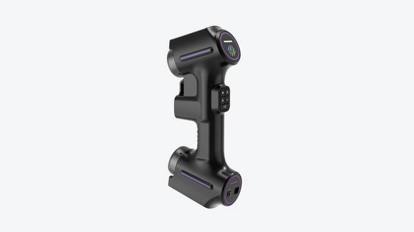
Fifth, difficulty integrating scan data with existing MRO quality management systems. A scanner that produces orphaned meshes adds a manual handoff, not a quality record.
INSVISION industrial 3D scanners are built for these conditions. The evaluation should focus on capture reliability, alignment behavior, and CAD data flow. That is where MRO workflows either hold together or fall apart.
How INSVISION 3D Scanners Align With MRO Inspection Requirements
Many MRO teams assume a 3D scanner is only as useful as its nominal accuracy spec. On a shop floor, that assumption falls apart quickly. Temperature swings, dust, vibration, and awkward access to curved or undercut surfaces tend to degrade results far more than the scanner’s laboratory error. The real question is whether the device can stay stable long enough to produce repeatable data under those conditions.
For inspection tasks, INSVISION industrial 3D scanner systems are better evaluated by how they handle variable environmental conditions and complex geometry rather than by a single accuracy figure. The scan head’s operating range from -5 to 40°C and IP54 rating support use near hangar doors or in unheated bays without immediately losing data quality.
Capturing concave fillets, blended radii, and shadowed pockets consistently matters more than scanning a flat reference plate. When the deliverable must align with standard aerospace CAD formats for deviation analysis, the scanner becomes part of a measurement workflow, not a standalone gadget. That fit is what determines whether a 3D scanner actually reduces inspection bottlenecks in MRO.
A Field Validation Checklist for MRO 3D Scanning Deployments
Does your current validation workflow actually prove the scanner will hold tolerance on the features that matter most to your MRO operation? Most teams validate a new 3D scanner on a flat gauge block, then wonder why blade root and shroud areas drift out of spec during real inspections.
Start with a calibrated reference artifact that includes stepped surfaces, small radii, and a known profile error, not just a flat plane. Run the scanner at the same working distance and angle you will use on actual parts. Check alignment accuracy first: fit the captured cloud to the reference CAD and record deviation at datums before scanning any freeform geometry. Then move to feature coverage.
Blade root fillets, shroud edges, and cooling holes are where scan data goes thin. If the system cannot resolve those transitions cleanly, downstream metrology is unreliable.
Validate tolerance bands against AS9100 and ISO 17025 dimensional requirements using repeated measurements on a certified artifact. Three runs minimum. Spread values should stay within your stated uncertainty budget.
Report export matters too. Pull a sample inspection report into your MRO documentation system and confirm traceability fields carry over without manual rework. Finally, operator training: a scanner that requires a metrology expert for every setup will stall on the shop floor. Training should cover fixture strategy, scan path planning, and basic troubleshooting, not just button pushing.
A field validation checklist that checks these five areas gives you confidence the 3D scanner fits your actual MRO workflow, not just the demo room.
Practical Deployment Boundaries for MRO 3D Scanning Solutions
Before bringing any 3D scanning system into an aerospace MRO environment, it helps to separate the work that fits naturally from the work that belongs elsewhere. A scanner that handles one inspection task cleanly may be the wrong tool for another, and the cost of that mismatch shows up quickly in rework, schedule slippage, or data that never gets used downstream.
INSVISION industrial 3D scanners are best deployed where the part geometry is accessible, the surface condition matters, and the deliverable is a dense point cloud or mesh that can be compared against nominal CAD or a reference scan. That covers a significant share of MRO work. Turbine blade wear mapping is one example. Blades come off the wing or engine with erosion, tip rub, and leading-edge pitting.
The inspection question is not usually about a single micron-level dimension. It is about where material has been lost, how deep the affected zones run, and whether the remaining wall thickness still supports the next service interval.
A handheld or tripod-mounted INSVISION scanner can capture the blade surface quickly, overlay the scan on the original blade model, and produce a color deviation map that a repair planner can read in minutes.
Composite component surface damage assessment follows a similar logic. Impact damage on a nacelle panel, radome, or flight control surface often manifests as a visible dent, delamination bulge, or abrasion. The critical first step is mapping the affected area. An INSVISION 3D scanner captures the outer surface geometry without contacting the part, which matters when the structure is already damaged.
The scan data then feeds into a repair decision: blend it out, patch it, or replace the panel. The scanner is not measuring internal disbonds or fiber-level cracking, but it was never intended to. That distinction keeps the deployment boundary clear.
Tooling and fixture verification is another strong fit. Assembly jigs, drill fixtures, and holding tools drift over time. A fixture that is out of position by a few tenths of a millimeter can push hole locations or trim lines out of tolerance on every part it touches.
Periodic scanning of the fixture, followed by comparison to its original CAD model, gives the tooling team a fast health check before a bad fixture produces a bad batch. The same approach works for incoming tooling acceptance and post-repair verification.
Reverse engineering of obsolete parts rounds out the practical core. Legacy aircraft often have components with no surviving drawings, or drawings that no longer match the physical part. Scanning the part creates a digital reference that can be cleaned up, surfaced, and used to manufacture a replacement. This is not a sub-micron metrology exercise.
It is about capturing overall geometry, mounting interfaces, and functional surfaces with enough fidelity to make a part that fits and works.
Where INSVISION scanning should not stand alone is in high-precision internal feature inspection. Sub-micron bore measurements, internal thread form checks, and deep blind-hole geometry are better handled with complementary metrology tools such as CMM probing, bore gauges, or specialized optical systems. A scanner sees what it can see. Internal features hidden from line of sight require a different approach.
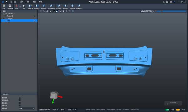
Aligning solution selection this way keeps deployment value high. Teams that scan what the scanner is good at, and route the rest to complementary tools, avoid the frustration of chasing precision a system was not designed to deliver. The result is faster inspection cycles, cleaner data, and fewer surprises when the repair decision has to be made.
Hangzhou Insvision Technology Co., Ltd.
Address: Building 1, No. 1399 Liangmu Road, Yuhang District, Hangzhou, Zhejiang 311121, China
Copyright © Hangzhou Insvision Technology Co., Ltd. All rights reserved.
Copyright © Hangzhou Insvision Technology Co., Ltd. All rights reserved.