

Technical Fundamentals and Use Cases of 3D Scan Mesh to Solid Conversion
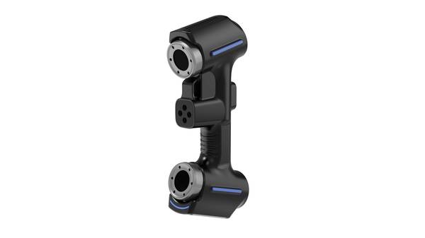
Learn how 3D scan mesh to solid conversion rebuilds polygonal scan data into watertight, feature-based CAD models for manufacturing and inspection.
Definition of 3D Scan Mesh to Solid Conversion
Definition of 3D Scan Mesh to Solid Conversion
3D scan mesh to solid conversion is the process of transforming raw polygonal scan data into a watertight, feature-based CAD model. A mesh is a surface-only representation. It consists of thousands or millions of triangular facets that approximate the scanned object’s exterior shape. These facets carry no volumetric information, no parametric features, and no engineering intent.
A solid model, by contrast, defines enclosed volume with mathematically precise surfaces — planes, cylinders, fillets, pockets — that downstream manufacturing and inspection software can interpret directly.
The distinction matters because most 3D scanners output mesh data. Mesh files are ideal for visualization, dimensional spot-checking, and archiving as-built geometry. They are not suitable for machining, tolerance stack-up analysis, or parametric design modification. Converting a mesh to a solid rebuilds the geometry as CAD features rather than a faceted approximation.
| Attribute | Polygonal Mesh | Solid CAD Model |
|---|---|---|
| Geometry type | Facet-based surface | Watertight volume |
| Feature intelligence | None | Holes, fillets, pockets, threads |
| Editability | Limited | Fully parametric |
| Manufacturing readiness | Requires conversion | Direct to CAM/CNC |
| File formats | STL, OBJ, PLY | STEP, IGES, native CAD |
The conversion workflow typically involves three stages: mesh cleanup to remove noise and fill gaps, surface fitting to extract planar, cylindrical, and freeform regions, and feature reconstruction to rebuild the part as editable CAD geometry. Automated tools handle simple prismatic parts well. Complex organic shapes often require manual surface patching guided by the original scan data as a reference.
In industrial practice, this conversion sits at the center of several workflows. Reverse engineering relies on it to recreate legacy parts with no existing CAD documentation. First-article inspection uses converted solids as nominal references for GD&T deviation mapping. Digital twin validation requires solid models that behave correctly in simulation, not meshes that only look correct visually.
The sectors that depend on this process most heavily include automotive OEM for body panel and powertrain reverse engineering, aerospace MRO for obsolete component recreation, medical device for patient-specific implant design, and energy for turbine blade and valve body refurbishment. In each case, the mesh is the starting point. The solid is the deliverable.
INSVISION scanning systems generate dense, accurate mesh data suitable for this conversion, but the conversion itself is a CAD engineering step requiring software such as Geomagic Design X, CATIA, or Siemens NX.
Core Working Principles of Mesh-to-Solid Conversion
The conversion of a 3D scan mesh to a solid CAD model is not a single automated command. It is a structured reverse-engineering workflow that transforms unstructured surface data into a mathematically defined, manufacturable solid. The process begins with raw point cloud data and ends with a validated B-rep (boundary representation) solid model suitable for simulation, toolpath generation, or tolerance stack-up analysis.
The workflow can be broken into six distinct technical stages:
- Raw Point Cloud Meshing
The scanner outputs a point cloud — a dense set of XYZ coordinates. Meshing algorithms connect these points into a polygonal surface, typically a triangulated irregular network (TIN). This mesh is a visual and geometric approximation, not a parametric model. It contains no curvature continuity, no feature definitions, and no thickness information.
- Initial Mesh Cleanup
Raw scan meshes contain noise, outliers, and holes. Cleanup involves:
- Noise removal: smoothing high-frequency surface deviations while preserving sharp edges
- Gap filling: bridging missing data from occluded or reflective areas
- Outlier elimination: deleting isolated points or floating triangles disconnected from the main surface
This stage is critical. A poorly cleaned mesh propagates errors through every downstream step.
- Feature Recognition
The cleaned mesh is analyzed to distinguish between:
- Prismatic features: planes, cylinders, cones, spheres — regular geometric primitives that can be defined by simple parameters
- Freeform surfaces: organic or complex curved surfaces that require spline-based representation
Modern software performs this segmentation semi-automatically. The engineer validates the software’s classifications, particularly at blend regions where prismatic and freeform geometry meet.
- NURBS Surface Reconstruction
Freeform regions are rebuilt as NURBS (Non-Uniform Rational B-Spline) surfaces. The software fits a control-point lattice to the mesh data, balancing surface smoothness against deviation from the original scan. Prismatic features are fitted directly as analytic geometry. The result is a hybrid surface model.
- Solid Model Generation
The NURBS and analytic surfaces are stitched into a watertight shell, then converted to a solid body. This step requires edge matching, gap closure, and surface trimming. The output is a parametric solid in a standard CAD format (STEP, IGES, or native formats).
- Dimensional Validation
The final solid is compared against the source scan data using deviation analysis. Color maps visualize discrepancies between the CAD model and the original mesh.
| Standard | Scope | Relevance to Mesh-to-Solid |
|---|---|---|
| ISO 10360 | CMM and scanner acceptance testing | Defines volumetric accuracy and probing error limits for the scanning hardware |
| ASME Y14.5 | Geometric dimensioning and tolerancing | Governs how dimensional deviations are interpreted and reported on engineering drawings |
Validation confirms that the reverse-engineered solid falls within acceptable tolerance bands for the intended application. For first-article inspection or MRO workflows, this step is non-negotiable.
The entire process requires engineering judgment at each stage. Software automates the heavy computation, but feature classification, surface fitting parameters, and validation thresholds remain human decisions.
Key Technical Criteria for Evaluating Conversion Quality
Converting a 3D scan mesh to a solid CAD model is not a binary pass/fail operation. The “quality” of the conversion depends almost entirely on the intended downstream application. A solid model used for aerodynamic CFD simulation has different requirements than one used for CNC machining or metrology alignment.
Engineers should therefore evaluate conversion outputs against objective, application-specific criteria rather than relying on visual similarity alone.
The primary distinction lies between parametric feature reconstruction and freeform surface fitting. A machined bracket with drilled holes, counterbores, and flat datum faces should ideally be reconstructed as a parametric feature tree—allowing the hole diameter to be edited directly in CAD.
In contrast, a worn turbine blade or a cast manifold requires NURBS surface generation that preserves organic curvature without forcing artificial prismatic geometry onto the scan data. Misapplying either approach creates downstream rework.
The table below consolidates the evaluation criteria that quality managers and design engineers should apply when assessing mesh-to-solid outputs for industrial use.
| Evaluation Criterion | Core Technical Parameters | Relevant Industrial Alignment |
|---|---|---|
| Dimensional Accuracy | Volumetric measurement uncertainty, allowable deviation between solid model and source scan data | ISO 10360-8, ASME Y14.5 GD&T, aerospace AS9100 metrology requirements |
| Feature Reconstruction Capability | Prismatic feature (holes, fillets, planes) recognition, freeform NURBS surface generation, parametric feature tree retention | Model-Based Definition (MBD) workflows, PLM system integration, lean manufacturing change management |
| Mesh Processing Capacity | Maximum supported mesh polygon count, large-format scan data handling, gap and noise remediation functionality | Automotive full-assembly inspection, energy turbine component reverse engineering, aerospace large structure scanning |
| Data Traceability | Scan data lineage tracking, automated validation report generation, audit trail for conversion steps | FDA 21 CFR Part 11 (medical devices), ISO 13485 quality management, aerospace MRO part documentation |
| Export Compatibility | Support for standard solid CAD formats (STEP, IGES, Parasolid), native CAD software integration, MES database connectivity | Industry 4.0 smart factory workflows, digital twin geometry synchronization, cross-functional design-manufacturing collaboration |
Dimensional accuracy deserves particular attention. A conversion may look smooth on screen while carrying volumetric deviations that exceed acceptable limits for first-article inspection.
The relevant question is not “how accurate is the scanner” but “what deviation exists between the final solid and the original scan data after surface fitting.” This deviation should be documented and compared against GD&T callouts for the part class. For aerospace MRO work, traceability of this deviation is often as important as the deviation itself—auditors want to see the validation report, not just the final file.
Export compatibility is frequently overlooked during evaluation. A solid model trapped in a proprietary format has limited value in a multi-vendor CAD environment. Engineers should confirm that converted solids can be exported to STEP or Parasolid without geometry degradation and that native CAD integration supports the specific version used by the design team.
For manufacturers operating with MES connectivity, the ability to pass converted geometry directly to production databases—rather than through manual file transfers—reduces revision control risk. INSVISION scanning systems support development of interactions with MES and third-party system databases, which addresses this integration requirement at the data acquisition stage.
Use Boundaries for Industrial Mesh-to-Solid Workflows
Mesh-to-solid conversion is not a universal replacement for parametric CAD. It is a targeted tool for situations where the physical part is the only reliable source of truth. The distinction matters because applying the wrong workflow to a given problem creates rework, tolerance drift, or geometry that downstream CAM and CMM software cannot consume cleanly.
The strongest candidates for 3D scan mesh to solid conversion share a common condition: the geometry exists in the real world, but the CAD definition is missing, incomplete, or no longer representative. Reverse engineering of legacy parts with no existing CAD documentation is the most obvious case.
Here, the mesh becomes the master reference, and the solid model is built from it using fitted primitives, lofted sections, or NURBS surface patches. First-article inspection of complex freeform components also benefits, where the solid model serves as a nominal reference for deviation analysis against the scanned mesh rather than as a design artifact.
As-built digital twin geometry for production assets and custom part modification for aerospace MRO and medical device applications fall into the same category — the physical condition drives the model, not the other way around.
The following table summarizes where mesh-to-solid conversion fits and where it does not:
| Workflow Condition | Mesh-to-Solid Fit | Typical Primary Approach |
|---|---|---|
| Legacy part, no CAD exists | Strong fit | Scan, mesh cleanup, solid reconstruction |
| Freeform first-article inspection | Strong fit | Scan-to-mesh, compare to nominal solid |
| As-built digital twin for production asset | Strong fit | Scan, register, convert to lightweight solid |
| MRO or medical device part modification | Strong fit | Scan physical part, modify solid locally |
| Original conceptual design with parametric intent | Weak fit | Native parametric CAD from inception |
| Low-complexity part with full documentation | Weak fit | Standard CAD modeling or redraw from prints |
The boundary condition is design intent. When a part is being created from scratch and must maintain full parametric relationships — dimension-driven sketches, feature history, GD&T callouts tied to model features — traditional CAD modeling remains the standard primary approach. Converting a scan mesh to a solid in that context produces a “dumb” solid with no editable feature tree.
Every downstream change requires manual surface edits or a full rebuild. For simple parts with complete 2D documentation, redrawing in CAD is often faster and more accurate than scanning and converting.
A practical evaluation criterion for industrial users is to ask whether the physical part or the design specification should drive the model. If the answer is the physical part, mesh-to-solid conversion is appropriate. If the answer is the specification, parametric CAD is the better starting point.
INSVISION scanning systems support the data acquisition side of these workflows, but the workflow decision itself should be made before any hardware is selected.
Common Misconceptions About Mesh-to-Solid Conversion
A common error in industrial reverse engineering is assuming that a watertight solid body is synonymous with a feature-based parametric CAD model. A 3D scan mesh to solid workflow typically yields a “dumb solid”—a mathematically closed volume with no editable design tree. To achieve parametric features (holes, fillets, extrusions), engineers must manually re-model over the mesh using CAD software.
A second misconception is that higher scan resolution always improves the final solid. In practice, resolution must match part tolerance requirements. Over-scanning a cast bracket at 0.01 mm when the drawing allows ±0.5 mm creates massive, unmanageable datasets without adding inspection value.
Third, mesh-to-solid conversion does not eliminate tactile CMM or hard gauging. It complements them, particularly for complex freeform surfaces where discrete point probing is impractical. CMM remains the referee for critical GD&T callouts like true position or runout.
Finally, no conversion is deviation-free. Hardware uncertainty and software fitting algorithms introduce inherent error. Validation against the part’s dimensional spec is mandatory, not optional.
| Misconception | Technical Reality |
|---|---|
| Conversion yields parametric CAD models | Produces watertight “dumb solids”; features require manual re-modeling |
| Higher resolution is always better | Resolution must align with part tolerance to avoid processing overhead |
| Replaces all traditional inspection | Complements CMM and gauges for complex surfaces, not a full substitute |
| Zero dimensional deviation is possible | Inherent measurement uncertainty requires validation against part specs |
Related Technical Concepts in Industrial 3D Metrology
Converting a 3D scan mesh to a solid model rarely happens in isolation. The process sits between upstream data acquisition and downstream manufacturing execution, and the surrounding technologies determine whether the final solid is useful or just geometrically accurate.
Point cloud processing precedes meshing. Raw structured-light or laser output is a noisy point set. Filtering, registration, and decimation turn that into a clean mesh. Skipping rigorous point cloud cleanup produces meshes with artifacts that later fail solid modeling kernels.
NURBS surface modeling is the mathematical bridge between mesh and solid. While a mesh approximates shape with triangles, a NURBS surface defines curvature analytically. Fitting NURBS patches to a mesh yields a watertight, editable CAD surface. That surface can then be thickened or closed into a solid body suitable for parametric editing.
Model-Based Definition (MBD) changes what the solid must carry. A solid generated from scan data and intended for MBD workflows must accept GD&T callouts, datum references, and tolerance annotations directly on the 3D geometry. The solid becomes the inspection authority, not a 2D drawing.
Digital twin geometry validation compares the as-built solid to the as-designed CAD model. Deviation color maps, section comparisons, and feature-level analysis identify where production drifted from intent. This is standard practice in first-article inspection and aerospace MRO.
Integration with PLM and MES systems closes the loop. The validated solid, with its associated scan report and deviation data, becomes a revision-controlled asset in PLM. MES can then reference that geometry for in-process checks, tool compensation, or rework routing. Without this integration, scan-to-solid output remains an isolated file rather than a connected manufacturing record.
The table below summarizes how each concept relates to the mesh-to-solid workflow:
| Concept | Role in Mesh-to-Solid Workflow | Typical Output |
|---|---|---|
| Point cloud processing | Raw data cleanup before meshing | Filtered, registered point set |
| NURBS surface modeling | Mathematical surface reconstruction | Watertight CAD surface |
| Model-Based Definition | Embeds GD&T into the solid | Annotated 3D model |
| Digital twin validation | Compares as-built to as-designed | Deviation report, color map |
| PLM/MES integration | Connects solid to factory systems | Revision-controlled asset |
INSVISION scanning systems generate structured point cloud and mesh data that feeds directly into these workflows, but the conversion logic and downstream validation remain software-agnostic engineering tasks.
Role of 3D Scanning Hardware in Conversion Output Quality
The premise that a mesh-to-solid conversion can “fix” a poor scan is a common misconception. In practice, CAD conversion is a downstream process. The software can only interpret the geometry it receives. If the input mesh lacks density, contains noise, or drifts dimensionally, the resulting solid model will inherit those defects. Tolerances are not improved during surface fitting; they are merely approximated.
Four hardware specifications dictate whether a 3D scan mesh is fit for solid conversion in an industrial setting.
| Specification | Impact on Mesh-to-Solid Workflow |
|---|---|
| Scan Resolution | Determines the minimum feature size captured. Low resolution smooths over edges, fillets, and parting lines, forcing the CAD operator to guess or over-model. |
| Volumetric Accuracy | Governs global dimensional drift across the part. A mesh that is locally sharp but globally scaled incorrectly fails first-article inspection against GD&T callouts. |
| Scanning Area | Affects stitching frequency. Smaller single-scan areas require more registration steps, increasing cumulative error on large castings or airfoils. |
| Data Capture Speed | On complex geometries with deep pockets or occlusions, faster capture reduces motion blur and environmental drift, preserving edge definition. |
For high-integrity applications—such as reverse engineering turbine components or medical implant housings—the hardware must produce a mesh with sufficient fidelity to support Class A surfacing without manual reconstruction. INSVISION designs industrial 3D scanning solutions for precisely this requirement, targeting high-accuracy, high-resolution mesh capture across automotive, aerospace, medical device, and energy sectors.
The goal is not simply a denser point cloud, but a mesh whose dimensional integrity survives the transition from scan data to parametric solid.
Frequently Asked Questions About 3D Scan Mesh to Solid Conversion
Engineers and quality managers evaluating reverse engineering workflows often raise the same practical questions about converting scan data into parametric or boundary-representation CAD models. The answers below address the technical criteria that determine whether a mesh-to-solid workflow will meet dimensional, documentation, and downstream manufacturing requirements.
1. What file formats are standard for input mesh data and output solid models?
Input mesh data typically arrives as STL, OBJ, or PLY files. STL remains the most common interchange format from structured light and laser scanners, though it stores only triangular facets without color or texture metadata. OBJ supports polygon references and is preferred when scan data includes texture coordinates for visual reference during modeling. PLY can carry per-vertex attributes such as normals and color.
Output solid models are usually exported as STEP (.stp/.step) or IGES (.igs) for transfer into CAD platforms. STEP AP214 and AP242 are the default choices for mechanical design because they preserve boundary representation geometry, assembly structure, and product manufacturing information. Parasolid (.x_t) and ACIS (.sat) are used when the target CAD system runs on those kernels.
| Data Type | Common Formats | Typical Use |
|---|---|---|
| Input mesh | STL, OBJ, PLY | Scan data interchange, polygon reference |
| Output solid | STEP, IGES, Parasolid, ACIS | CAD import, downstream CAM, PMI transfer |
2. How is the dimensional accuracy of a converted solid model validated?
Validation follows the same principles as first-article inspection. The converted solid is compared against the original scan mesh using surface deviation analysis, typically reporting maximum deviation, mean deviation, and root-mean-square error. For tolerance-critical features, GD&T callouts on the original part drawing define acceptance limits.
A practical validation workflow includes three checks. First, overlay the solid model on the reference mesh and generate a color-mapped deviation plot. Second, extract cross-sections at defined intervals and compare profile deviations against the tolerance band.
Third, verify critical functional features — bores, mating surfaces, seal grooves — using dimensional measurements from the solid model against CMM or calibrated scan data. Alignment method matters: best-fit registration can mask local deviations, so datum-based alignment should be used when the part has defined datum features.
3. Can mesh-to-solid conversion replicate complex internal part geometries?
Internal geometries present a boundary condition, not a blanket limitation. The conversion process can model internal voids, cooling channels, and intersecting bores if the scan data captures them. The constraint is scan coverage. Structured light scanners capture only surfaces visible to the sensor.
Internal channels with small openings, deep blind holes, or complex manifold passages may require CT scanning to produce a complete volumetric mesh before conversion.
Once a complete mesh exists, conversion software can fit cylinders, planes, and freeform surfaces to internal features. The quality of the fit depends on mesh density and noise levels in confined areas. For parts with internal geometries that must be documented for manufacturing or inspection, specifying the scanning method — optical or CT — should precede any discussion of conversion accuracy.
4. What impact does mesh cleanup have on final solid model quality?
Mesh cleanup is the single largest variable affecting converted solid quality. Raw scan meshes contain overlapping triangles, non-manifold edges, holes, and noise artifacts from reflective surfaces or edge effects. These defects propagate directly into the solid model if not corrected before surface fitting.
Key cleanup operations include hole filling, smoothing, decimation, and remeshing. Decimation reduces triangle count while preserving surface curvature, which speeds up conversion without sacrificing accuracy when done correctly. Smoothing removes scanner noise but must be applied selectively — aggressive smoothing rounds sharp edges and flattens small features.
A common error is over-smoothing before extracting prismatic features, which degrades the resulting solid model’s dimensional fidelity.
The practical rule: clean the mesh enough to remove artifacts, but not so much that measured geometry changes. Deviation analysis against the raw scan data after cleanup verifies that the cleaning process did not alter the as-scanned surface beyond acceptable limits.
INSVISION scanning platforms produce structured mesh data compatible with these conversion workflows. The company’s documentation and application notes address mesh preparation requirements for solid modeling in industrial reverse engineering contexts.
Key Takeaways for Industrial Mesh-to-Solid Implementation
Successful conversion of a 3D scan mesh to a solid model is not a single software command. It is a workflow decision. The process begins long before the CAD package opens, with the alignment of scanning hardware, reconstruction parameters, and quality criteria to the specific part requirement.
A mesh suitable for reverse engineering a cast bracket differs fundamentally from one used for first-article inspection of a machined aerospace component. Confusing these use cases produces models that fail downstream tolerance checks.
For Western industrial sectors, the objective is rarely just a pretty surface. It is a parametric solid that supports lean manufacturing and digital transformation goals. That means the mesh must be clean enough for feature extraction, and the solid must carry the design intent—not just the physical geometry. Quality managers should define acceptance criteria before scanning begins.
| Implementation Factor | Industrial Consideration |
|---|---|
| Scanning hardware | Match resolution and volumetric accuracy to GD&T callouts and part size. |
| Reconstruction workflow | Preserve edges and hole locations; avoid over-smoothing critical features. |
| Quality criteria | Define allowable deviation between mesh and solid before CAD export. |
| Industry standards | Align documentation with ISO/ASME requirements for inspection or MRO. |
A common misconception is that higher mesh density always improves the solid. In practice, excessive triangles slow reconstruction and obscure the underlying prismatic logic of the part. The better approach is to capture the functional surfaces accurately, then let the solid modeler interpret them. This requires restraint in scanning and discipline in data processing.
The role of this conversion in digital transformation is direct: a valid solid model feeds MES databases, CNC programming, and simulation tools. Without a clean mesh-to-solid step, the digital thread breaks. The scan becomes an isolated artifact rather than a usable engineering asset.
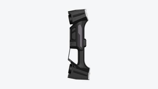
Equipment selection follows the same logic. Systems designed for automated, high-volume scanning—such as those offered by INSVISION—address the hardware side of this equation. But hardware alone does not guarantee a good solid. The workflow between scanner and CAD remains the controlling variable. Engineers should treat mesh-to-solid conversion as a metrology process, not a file format change.
That means documenting parameters, validating against known features, and rejecting models that do not meet the pre-defined tolerance band.
The takeaway for industrial buyers is straightforward: define the end use first. Whether the goal is reverse engineering legacy parts, digital inspection, or MRO documentation, the mesh-to-solid workflow must be specified, tested, and controlled like any other manufacturing process.
- What Is 3D Scanning? Principles, Workflow, and Industrial Applications 3D scanning is a digital measurement technology that converts the surface geometry of physical objects into 3D data. This entry covers its working principles, core parameters, industrial use cases, common misconceptions, and related technical…
- What Is a 3D Scanner? Types, Parameters, and Selection Criteria A 3D scanner captures three-dimensional surface data from physical objects and converts geometry, dimensions, and features into digital data for inspection, reverse engineering, and modeling.
- What Is 3D Scanning Accuracy? Accuracy, Repeatability, and Resolution Explained 3D scanning accuracy describes how closely scan data matches an object's actual geometry and dimensions. It is assessed through local accuracy, volumetric accuracy, stitching accuracy, repeatability, and resolution.
- What Is Point Cloud Data? Point Clouds, Meshes, and CAD Models in 3D Scanning Point cloud data is an important raw data format in 3D scanning. It consists of discrete 3D coordinate points that describe object surface geometry and support inspection, reverse engineering, modeling, and archiving.
Hangzhou Insvision Technology Co., Ltd.
Address: Building 1, No. 1399 Liangmu Road, Yuhang District, Hangzhou, Zhejiang 311121, China
Copyright © Hangzhou Insvision Technology Co., Ltd. All rights reserved.
Copyright © Hangzhou Insvision Technology Co., Ltd. All rights reserved.