

3D Scanner High Accuracy Standards, Principles, and Use Cases
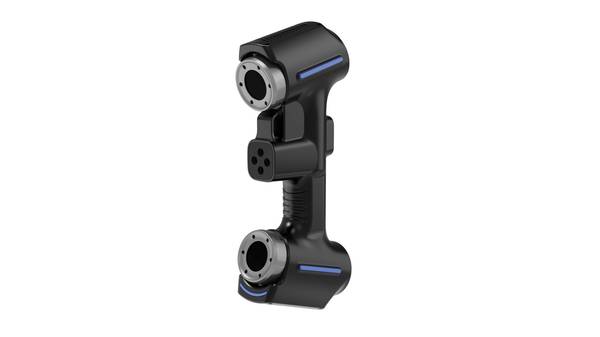
Learn how a 3D scanner high accuracy is defined, validated, and applied in industrial metrology for inspection and tooling verification.
What Is High Accuracy 3D Scanning?
What Is High Accuracy 3D Scanning?
High accuracy 3D scanning is a non-contact, metrology-grade measurement technology that captures the surface geometry of a physical part as dense, coordinate-defined point cloud data.
Unlike general-purpose 3D scanners built for visualization, reverse engineering of organic shapes, or consumer applications, high accuracy systems are engineered to produce measurements that can be trusted for dimensional inspection, first-article validation, and tooling correction.
The distinction matters. A design-focused scanner may produce visually convincing meshes while carrying volumetric errors of several tenths of a millimeter — unacceptable when a GD&T callout specifies a ±0.05 mm profile tolerance. Metrology-grade scanners are validated against traceable artifacts and must demonstrate repeatable, quantified uncertainty across their measurement volume.
In Western industrial markets, two frameworks anchor this validation. ISO 10360 defines acceptance and reverification tests for coordinate measuring systems, including laser-based 3D scanners. The ASME V&V (Verification and Validation) 3D standards establish protocols for evaluating the performance of non-contact dimensional measurement systems against reference data.
A scanner marketed as “high accuracy” without reference to these frameworks should be evaluated with skepticism.
The table below summarizes the core distinctions:
| Criterion | High Accuracy Industrial 3D Scanner | General-Purpose / Design 3D Scanner |
|---|---|---|
| Primary output | Traceable dimensional point cloud for inspection | Visual mesh or CAD-ready surface |
| Typical volumetric accuracy | Sub-0.1 mm, often expressed with length-dependent terms (e.g., 0.015 mm + 0.035 mm/m) | 0.1–0.5 mm or unspecified |
| Validation framework | ISO 10360, ASME V&V 3D | Manufacturer-internal or none |
| Typical use cases | First-article inspection, tooling verification, MRO dimensional checks | Concept modeling, animation, hobbyist scanning |
| Environmental compensation | Temperature, vibration, and scale-bar correction considered | Minimal or absent |
High accuracy scanning has become a practical bridge between traditional CMM inspection and the throughput demands of modern production lines. Where a touch-probe CMM measures discrete points slowly, a metrology-grade 3D scanner captures millions of points in minutes, enabling full-surface comparison against CAD nominal data.
This capability is particularly relevant in automotive OEM, aerospace MRO, medical device manufacturing, and energy sector applications, where surface form, wear, and deformation must be quantified rather than visually approximated.
Accuracy claims, however, require careful reading. A single-point accuracy specification does not describe performance across a large scan volume. Length-dependent volumetric accuracy terms — expressed as a fixed offset plus a per-meter error component — provide a more honest representation of real-world performance. Scale-bar photogrammetry can further constrain accumulated error on large parts.
Engineers evaluating such systems should request validation reports referencing recognized standards, not marketing summaries.
Core Operating Principles of High Accuracy 3D Scanners
High accuracy in non-contact metrology is not a single technology but the result of specific optical measurement principles applied under controlled conditions. For industrial buyers evaluating a 3D scanner with high accuracy claims, understanding the underlying approach matters more than the headline specification.
Practical Workflow
- Core Operating Principles of High Accuracy 3D Scanners — High accuracy in non-contact metrology is not a single technology but the result of specific optical measurement principles appli…
- Key Parameters for Evaluating 3D Scanner High Accuracy Pe… — Accuracy specifications on a datasheet rarely tell the full story.
- Appropriate Use Cases for High Accuracy 3D Scanners — High accuracy 3D scanning refers to non-contact optical measurement capable of capturing dense surface data within a tight tolera…
- Common Misconceptions About High Accuracy 3D Scanning — “High accuracy” is one of the most misused terms in industrial metrology.
Structured light projection works by projecting a known pattern — typically a series of fringes or a speckle field — onto a surface. One or more cameras observe how the pattern deforms across the geometry. Because the projector and camera positions are fixed and calibrated, the system triangulates millions of points per frame.
This method excels at capturing dense surface data quickly, making it well suited to freeform surfaces, castings, and sheet metal where contact probing would be slow or impractical.
Laser triangulation relies on a laser line or point swept across a part. A camera positioned at a known angle records the laser profile, and each profile is stitched into a continuous point cloud. This approach performs well on reflective or dark surfaces that can challenge structured light systems, and it is common in automated inspection cells where repeatability under factory lighting matters.
Photogrammetric referencing addresses a different problem: volumetric error accumulation. When scanning large parts, small angular errors compound over distance. Adding coded targets and calibrated scale bars lets the system anchor local scans to a global reference frame.
The effect on accuracy is measurable — volumetric accuracy figures typically improve when working with a photogrammetric scale bar, reducing drift across meter-scale objects.
| Technology | Primary Strength | Typical Use Case | Accuracy Driver |
|---|---|---|---|
| Structured light | Dense, fast surface capture | Freeform geometry, castings, sheet metal | Calibrated projector-camera geometry |
| Laser triangulation | Performance on reflective/dark surfaces | Automated inspection cells, shiny parts | Stable laser plane and camera angle |
| Photogrammetric referencing | Global accuracy across large volumes | Automotive body panels, aerospace tooling | Coded targets and calibrated scale bars |
None of these methods requires physical contact with the part. That is the key distinction from CMM probing: the scanner measures surface coordinates optically, eliminating probe deflection, part deformation, and wear-related drift. The trade-off is sensitivity to surface finish, ambient light, and part fixturing — variables that a CMM operator rarely considers but which directly affect scan quality.
For micron-level work, the specification language matters. Single-point accuracy values describe local measurement capability. Volumetric accuracy — often expressed as a base value plus a length-dependent term, such as 0.015 mm + 0.035 mm/m — tells you how error scales with part size.
A scanner that meets a 0.020 mm local accuracy spec may still drift several tenths of a millimeter across a two-meter part unless a photogrammetric reference frame is applied.
The practical takeaway for quality engineers is straightforward: match the measurement principle to the part geometry, surface condition, and inspection volume. High accuracy claims mean little without understanding which technology produced them and under what conditions they hold.
Key Parameters for Evaluating 3D Scanner High Accuracy Performance
Accuracy specifications on a datasheet rarely tell the full story. An engineer evaluating a 3D scanner for high-accuracy applications needs to understand which parameter matters for a given measurement task, how each one is derived, and what happens to the numbers when the part gets larger or the environment changes.
A scanner that performs well on a small calibration artifact may drift noticeably across a full automotive panel. Conversely, a system with strong volumetric performance may still struggle to resolve micro-features on a medical implant. The distinction lies in how the accuracy is defined and verified.
The table below breaks down the four parameters that procurement teams and quality managers most often evaluate when qualifying a 3D scanner for industrial metrology work.
| Parameter | Technical Definition | Industrial Application Relevance |
|---|---|---|
| Single-Scan Accuracy | The maximum allowable deviation between a measured point on a calibrated reference artifact and its known true value, captured in a single, unmerged scan pass | Critical for small-part inspection where local feature precision (e.g., micro holes, edge profiles, surface textures) is a primary requirement, such as medical device implants or precision aerospace fasteners |
| Volumetric Accuracy | The total measurement uncertainty across the full usable scanning volume, accounting for positional drift, scaling errors, and geometric distortion across larger measurement distances | Essential for large-part metrology applications, such as automotive body panel alignment or aerospace turbine assembly validation, where consistent precision must be maintained across entire component dimensions |
| Projection Accuracy | The precision of structured light patterns (e.g., fringe patterns) projected onto a part’s surface to enable 3D point cloud reconstruction | Key for projection-based 3D scanning systems used in high-throughput quality control lines, where consistent pattern fidelity directly impacts the reliability of repeated measurements |
| Calibration Traceability | The documented, unbroken chain of calibrations linking a scanner’s accuracy measurements to national or international metrology standards (e.g., ISO 17025-accredited calibration artifacts) | Mandatory for regulated industries such as aerospace MRO and medical device manufacturing, where measurement data must comply with ISO 10360 or ASME V&V 3D standards |
Single-scan accuracy describes what the sensor can resolve in one capture. It is the number most often quoted in marketing material, and for good reason—it reflects the core optical and algorithmic performance of the system. But it does not account for what happens when multiple scans are stitched together. Stitching errors accumulate.
A scanner may hold 0.020 mm on a single pass yet drift to 0.080 mm across a meter-long part once alignment errors compound.
That is where volumetric accuracy enters. Expressed in formats like “0.015 mm + 0.035 mm/m,” this specification tells you how uncertainty scales with distance from the scanner or across the measurement volume. The additive term represents a fixed baseline error; the slope term scales with part size. For large aerospace structures or energy components, the slope term dominates and becomes the deciding factor.
Projection accuracy applies specifically to structured light systems. The projector casts fringe patterns onto the surface, and the scanner triangulates based on how those patterns deform. If the projected pattern itself is distorted or imprecise, every downstream calculation inherits that error.
Maximum projection error values—often in the range of 0.25 mm to 0.5 mm depending on the projector class—may seem large relative to scanner accuracy figures, but they interact with the triangulation geometry in ways that amplify or suppress the final point cloud error.
Calibration traceability is less about performance and more about defensibility. In regulated environments, a scanner is not “accurate” unless that accuracy can be proven against a recognized standard. ISO 17025-accredited artifacts, certified reference spheres, and documented calibration intervals all feed into this requirement.
Quality managers in aerospace MRO and medical device manufacturing treat traceability as non-negotiable, because audit findings hinge on it.
One common misconception is that a lower single-scan accuracy number automatically means a better scanner. In practice, the right parameter to prioritize depends on the part size, feature size, and inspection workflow. A system with slightly worse single-scan figures but superior volumetric behavior may deliver better results on large weldments or castings.
The evaluation should start with the measurement task, not the datasheet.
Appropriate Use Cases for High Accuracy 3D Scanners
High accuracy 3D scanning refers to non-contact optical measurement capable of capturing dense surface data within a tight tolerance band, typically under 0.050 mm. This capability defines a clear set of industrial applications where the technology delivers maximum value. The common thread across these scenarios is a need to quantify complex geometry quickly without touching the part.
The following table outlines the primary application fit by sector:
| Industry Sector | Best-Suited Application | Value Driver |
|---|---|---|
| Automotive OEM | Precision component inspection | Dense data supports GD&T callouts and first-article inspection on castings and stamped parts. |
| Aerospace MRO | Damage assessment and reverse engineering | Non-contact capture of airfoil blends and dent profiles on thin-walled components. |
| Medical Device | Implant quality control | Full-surface verification of freeform orthopedic implants where tactile probing is slow. |
| Energy | Turbine blade metrology | Streamlined workflow for capturing leading-edge profiles and airfoil twist. |
In these contexts, a high accuracy 3D scanner complements legacy contact metrology workflows. Where a coordinate measuring machine excels at discrete point verification, optical scanning provides full-field data. This is particularly relevant for reverse engineering legacy parts with no CAD model, or for mapping localized wear and distortion across a large surface.
The non-contact principle also eliminates probe deflection on soft or delicate materials, making it well suited for polymer medical components and thin aerospace sheet metal. For quality managers, the primary advantage is not replacing existing tools but extending measurement coverage into areas where dense data and rapid setup are required.
Common Misconceptions About High Accuracy 3D Scanning
“High accuracy” is one of the most misused terms in industrial metrology. Buyers routinely over-weight a single specification sheet figure while ignoring how that number behaves under real measurement conditions. Three assumptions cause most of the trouble.
Misconception 1: Single-scan accuracy guarantees reliable large-part measurements
A scanner may report 0.020 mm accuracy on a small reference artifact. That does not mean it will hold 0.020 mm across a 2-meter automotive body panel or a large aerospace tool. Large-part measurement introduces error stacking: each scan alignment adds uncertainty, and thermal expansion, part fixturing, and operator technique all contribute. This is why volumetric accuracy statements exist.
They express accuracy as a base value plus a length-dependent term — for example, “0.015 mm + 0.035 mm/m.” A part measured at 3 meters carries a different uncertainty budget than one measured at 300 mm. Ignoring the length-dependent term is the single fastest way to sign off on a scanner that fails first-article inspection downstream.
Misconception 2: A “high accuracy” label means the scanner meets international metrology standards
No universal regulatory body certifies a scanner as “high accuracy” before it ships. The label is marketing shorthand unless backed by documented, traceable verification against recognized standards such as VDI/VDE 2634 or ISO 10360. These standards define acceptance tests using calibrated artifacts, specific measurement procedures, and statistical evaluation of deviations.
A scanner without a traceable calibration certificate and a defined testing protocol has not proven anything. Engineering teams should ask one question before procurement: “Which standard was used, and where is the certificate?” If the answer is vague, the accuracy claim is unverified regardless of what the brochure says.
Misconception 3: One performance metric is enough for validation
Accuracy alone tells you how close a measured point is to its true position. It says nothing about repeatability, point spacing, edge sharpness, or sensitivity to surface finish. Two scanners can share an identical accuracy figure and perform very differently on shiny machined aluminum versus dark cast iron.
| Metric | What it tells you | Why it matters |
|---|---|---|
| Single-point accuracy | Deviation from a calibrated reference | Baseline capability on small features |
| Volumetric accuracy | Error growth with part size | Predicts large-part performance |
| Repeatability | Spread of repeated measurements | Separates stable results from luck |
| Point spacing / resolution | Smallest feature the scanner can resolve | Determines usable detail for GD&T callouts |
| Surface sensitivity | Behavior on reflective, dark, or textured surfaces | Real parts are rarely matte white |
A scanner that looks excellent on one row of this table may fail on another. Validation requires testing against your actual part geometry and surface conditions, not a vendor demo block.
INSVISION engineers its scanning systems to deliver documented, standards-aligned accuracy across these criteria, with published base and length-dependent accuracy values so engineering teams can calculate uncertainty budgets rather than guess at them.
Related Metrology Concepts for High Accuracy 3D Scanning
Achieving reliable results with a high accuracy 3D scanner requires more than a tight single-point specification. Engineers must account for how error accumulates across the measurement volume. Volumetric accuracy—often expressed as a base value plus a length-dependent term (e.g., 0.015 mm + 0.035 mm/m)—describes this behavior. It is a more honest indicator of real-world performance than a lone point accuracy figure.
Photogrammetric scale bar referencing reduces length-dependent drift on large parts. By encoding known reference distances into the scan project, the system corrects scale error before dense scanning begins. This is standard practice in aerospace MRO and large tooling inspection.
| Concept | What It Controls | Relevant Standard |
|---|---|---|
| Measurement uncertainty | Total error budget for a result | ISO/IEC 17025, ISO 14253 |
| Volumetric error mapping | Spatial error across the volume | ASME B89.4.22 |
| Scale bar referencing | Length accuracy on large objects | VDI/VDE 2634 |
| Calibration interval planning | Long-term traceability | ISO 9001, ISO 10012 |
Calibration interval planning closes the loop. A scanner verified against a certified artifact today may drift tomorrow. Western quality systems typically tie intervals to usage, environment, and risk—not vendor marketing claims.
INSVISION High Accuracy 3D Scanning Solutions
INSVISION High Accuracy 3D Scanning Solutions
INSVISION develops metrology-grade 3D scanning systems for industrial measurement and inspection applications. The company’s portfolio addresses the requirements of precision sectors where dimensional verification, process control, and part qualification depend on repeatable measurement data.
The product range includes structured light scanners and related optical measurement tools. Confirmed accuracy specifications across the portfolio reflect a design emphasis on metrology performance. Several scanner configurations achieve accuracy values up to 0.020 mm, with volumetric accuracy specifications of 0.015 mm + 0.035 mm/m under standard operating conditions.
When used with a photogrammetric scale bar, the same systems can achieve 0.015 mm + 0.025 mm/m. These figures indicate the performance envelope available for applications requiring tight dimensional tolerance verification.
| Measurement Parameter | Reported Value |
|---|---|
| Scanner accuracy (select systems) | Up to 0.020 mm |
| Volumetric accuracy (standard) | 0.015 mm + 0.035 mm/m |
| Volumetric accuracy (with scale bar) | 0.015 mm + 0.025 mm/m |
| Large-area scanner accuracy | Up to 0.073 mm |
The systems are positioned for quality control, inspection, and reverse engineering workflows in automotive OEM production, aerospace MRO, medical device manufacturing, and energy sector applications. These environments typically require alignment with recognized industrial metrology practices and documentation standards.
INSVISION stated focus on metrology-grade performance suggests an orientation toward ISO and ASME dimensional inspection frameworks rather than general-purpose or consumer scanning applications.
For engineers and quality managers evaluating high-accuracy 3D scanning technology, the relevant criteria include not only single-point accuracy but also volumetric accuracy across the measurement envelope, since larger parts introduce scaling errors that single-point specifications do not capture.
The distinction between scanner accuracy and volumetric accuracy matters in practice: a scanner may resolve fine surface detail at close range while accumulating error over extended scan paths. Systems that specify volumetric accuracy provide a more complete picture of performance on production-scale components.
Frequently Asked Questions About High Accuracy 3D Scanners
What accuracy threshold qualifies a 3D scanner as high accuracy for industrial use?
Industrial metrology draws a practical line around 0.050 mm. Systems claiming single-scan accuracy at or below this threshold are generally candidates for precision work—first-article inspection, tooling verification, or wear analysis. But the number alone is insufficient. A scanner spec of 0.020 mm means little without a defined measurement volume, surface condition, and traceability path.
Engineers should ask for the test method behind the figure, not just the figure itself.
How does volumetric accuracy differ from single-scan accuracy?
Single-scan accuracy describes error within one captured frame. Volumetric accuracy describes error across the entire measurement volume—and it grows with part size. A scanner might hold 0.020 mm locally but drift 0.035 mm per meter across a large casting. For parts over 500 mm, volumetric accuracy matters more than the single-scan spec.
| Parameter | What It Measures | Relevant For |
|---|---|---|
| Single-scan accuracy | Error within one frame | Small features, local detail |
| Volumetric accuracy | Error across full measurement volume | Large parts, assembly alignment, GD&T callouts |
Can high accuracy 3D scanners be used in regulated industrial sectors?
Yes, when validation is documented. Aerospace MRO, medical device, and energy sectors accept 3D scanning data where the system has been qualified against known artifacts and the measurement uncertainty is understood. The scanner itself does not carry ISO or ASME approval—the process does. Procurement teams should require a documented accuracy verification procedure rather than relying on a manufacturer’s spec sheet.
What role does photogrammetry play in improving high accuracy 3D scanning performance?
Photogrammetry provides a global reference frame. By capturing coded targets across a large part, it constrains volumetric error that would otherwise accumulate scan by scan. The result is tighter control on long-range dimensions. Some systems list volumetric accuracy figures with and without photogrammetric scale bars—the difference is measurable and worth reviewing before purchase.
Core Takeaways on High Accuracy 3D Scanning
Core Takeaways on High Accuracy 3D Scanning
In metrology, “high accuracy” is a relative term, not an absolute label. The suitability of a 3D scanner for a given task depends on the dimensional tolerance of the part, the required volumetric envelope, and the environmental conditions of the inspection cell. A scanner that is over-specified for a rough casting can be as impractical as one that is under-specified for a turbine blade root.
Selection should therefore be driven by use case-specific requirements. For example, a system with a single-point accuracy of up to 0.020 mm addresses tight GD&T callouts on small to medium components, while large-area projection systems may operate with maximum projection accuracies between 0.25 mm and 0.5 mm.
The relevant metric is not just the scanner’s base accuracy, but its volumetric accuracy across the entire measurement volume, often expressed as a base value plus a scale factor per meter (e.g., 0.015 mm + 0.035 mm/m).
Key evaluation criteria:
| Parameter | What it tells you |
|---|---|
| Single-point accuracy | Deviation at a specific point under controlled conditions |
| Volumetric accuracy | Error growth across the measurement volume |
| Traceability | Whether results are linked to national or international standards |
| Compliance | Conformance to ISO or ASME metrology frameworks |
A common misconception is that a smaller published accuracy figure always indicates a better system. In practice, validated, traceable performance parameters matter more than generic marketing labels. An accuracy specification without a defined measurement volume, temperature range, or reference standard is not a reliable basis for procurement.
Engineers should request calibration certificates and verify that the system’s performance has been characterized under conditions similar to their own production floor.
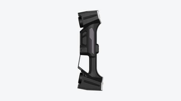
High accuracy 3D scanning functions as a versatile metrology tool across precision industrial applications—from first-article inspection in automotive OEMs to MRO workflows in aerospace and dimensional validation in medical device manufacturing. The technology replaces time-consuming manual gauging where complex freeform surfaces or dense point clouds are required.
However, the value of the data depends entirely on how the system’s accuracy is defined, validated, and matched to the tolerance band of the part being measured.
- What Is 3D Scanning? Principles, Workflow, and Industrial Applications 3D scanning is a digital measurement technology that converts the surface geometry of physical objects into 3D data. This entry covers its working principles, core parameters, industrial use cases, common misconceptions, and related technical…
- What Is a 3D Scanner? Types, Parameters, and Selection Criteria A 3D scanner captures three-dimensional surface data from physical objects and converts geometry, dimensions, and features into digital data for inspection, reverse engineering, and modeling.
- What Is 3D Scanning Accuracy? Accuracy, Repeatability, and Resolution Explained 3D scanning accuracy describes how closely scan data matches an object's actual geometry and dimensions. It is assessed through local accuracy, volumetric accuracy, stitching accuracy, repeatability, and resolution.
- What Is Point Cloud Data? Point Clouds, Meshes, and CAD Models in 3D Scanning Point cloud data is an important raw data format in 3D scanning. It consists of discrete 3D coordinate points that describe object surface geometry and support inspection, reverse engineering, modeling, and archiving.
Hangzhou Insvision Technology Co., Ltd.
Address: Building 1, No. 1399 Liangmu Road, Yuhang District, Hangzhou, Zhejiang 311121, China
Copyright © Hangzhou Insvision Technology Co., Ltd. All rights reserved.
Copyright © Hangzhou Insvision Technology Co., Ltd. All rights reserved.