

How to Validate 3D Component Scanning for Precision Part Inspection
Learn how to validate 3D component scanning on real part geometries, surface finishes, and shop floor conditions to ensure reliable precision inspection.
Your Precision Part Inspection Task: Where 3D Scanning Validation Goes Wrong
Most quality managers assume the hard part of adopting 3D component scanning is choosing the right hardware. It is not. The decision most likely to be misjudged happens before any purchase order is signed: trusting a generic supplier spec sheet instead of validating how a scanner actually handles your part geometries, surface finishes, and shop floor conditions.
A scanner that performs beautifully on a matte, sandblasted aluminum bracket in a demo lab can fall apart on a polished turbine blade root under mixed lighting near a machining cell. If you are running first-article inspection on aerospace MRO components, incoming checks on medical implants, or in-process verification of energy sector parts, the real question is not whether 3D scanning works.
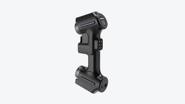
It is whether the system you select can hold tolerance on your specific GD&T callouts while surviving your actual environment. INSVISION industrial 3D scanners are built for these tasks, but even the right equipment fails if validation criteria are vague. Build your checklist around real parts, not marketing sheets.
Selection Dimensions and Field Checks
| Focus Area | Decision Point | Deployment Note |
|---|---|---|
| Your Precision Part Inspection Task: Where 3D Scanning… | Most quality managers assume the hard part of adopting 3D component scanning is choosing the right hardware. | It is not. |
| Core Pain Points of Unvalidated 3D Component Scanning R… | The key takeaway is simple: most 3D component scanning failures on the shop floor are not hardware problems. | They are validation problems. |
| 4 Non-Negotiable Validation Criteria for 3D Component S… | Are you certain your current 3D component scanning candidate can actually hold tolerance on the parts you build, not just the demo block the supplier… | The evaluation that matters happens on your own production floor. |
| Part Feature & Material Compatibility | Test the scanner on your most difficult production parts. | That means fine cooling holes on turbine blades, reflective aluminum drivetrain housings, or translucent polymer medical components. |
Core Pain Points of Unvalidated 3D Component Scanning Rollouts
The key takeaway is simple: most 3D component scanning failures on the shop floor are not hardware problems. They are validation problems. Teams buy a capable scanner, point it at a part, and expect the data pipeline to just work. It rarely does.
What gets missed is the part-specific validation step, where scan strategy, surface preparation, data export, and environmental tolerance are tested against the actual component and the actual inspection workflow. Skip that step, and the result is rework, bottlenecks, and a tool that quality engineers stop trusting.
This section breaks down four pain points that show up repeatedly when 3D component scanning is deployed without targeted validation.
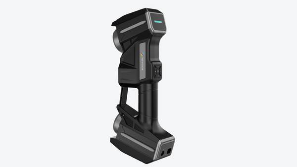
The first pain point is inconsistent scan data on complex or high-reflectivity parts. A machined aluminum housing with polished sealing surfaces will behave very differently from a cast iron bracket with a rough as-cast texture. Without validating exposure settings, scan angles, and possible matting spray on the specific part, operators end up with noisy point clouds around edges, holes, and shiny surfaces.
The scanner captures data, but the mesh has gaps or artifacts. Quality engineers then spend hours manually cleaning and patching the data before any dimensional analysis can happen. That manual rework undermines the whole reason for bringing in 3D component scanning in the first place.
The second pain point is workflow bottlenecks caused by misaligned scan and analysis speed relative to production takt time. A scanner that takes four minutes to capture a part may be fine for a low-volume aerospace MRO job. The same scanner becomes a constraint when it sits in a cell that needs a first-article check every twenty minutes.
Without validating cycle time against the actual inspection sequence, including part setup, scanning, mesh processing, and GD&T evaluation, teams discover too late that the system cannot keep pace. The result is a queue at the scanner, delayed buyoffs, and pressure on operators to skip steps just to keep production moving.
The third pain point is compatibility gaps between scan data exports and existing QMS or CAD software. Many teams assume a point cloud or STL file will drop into their current inspection workflow. That assumption fails when the CAD package expects a watertight mesh, or the QMS requires a specific report format tied to ballooned drawing callouts.
Without validating the export format and downstream data flow on the actual part file, teams end up writing custom scripts, manually converting files, or maintaining parallel spreadsheets. These workarounds delay integration with Industry 4.0 data pipelines and create version control problems that are difficult to unwind later.
The fourth pain point is unplanned downtime from solutions not built for industrial shop floor conditions. Temperature swings near a heat treat area, dust from a deburring station, or vibration from a nearby press can all affect scan repeatability and hardware reliability. A scanner that works in a metrology lab may struggle when mounted next to a machining cell.
Without validating the installation location and environmental conditions against the actual production environment, teams see drift in scan results, repeated recalibration, and unexpected failures that reduce overall equipment effectiveness.
INSVISION addresses these pain points by treating 3D component scanning as an application-specific validation exercise rather than a generic hardware purchase. The approach starts with the scan object, the inspection task, and the required data deliverable, then works backward to define the scan strategy, environmental setup, and export workflow.
For Western manufacturers running lean operations, that is the difference between a scanner that sits on a shelf and one that becomes part of the daily quality loop.
4 Non-Negotiable Validation Criteria for 3D Component Scanning
Are you certain your current 3D component scanning candidate can actually hold tolerance on the parts you build, not just the demo block the supplier brought in? The evaluation that matters happens on your own production floor. We recommend four non-negotiable validation criteria before any purchase decision.
Part Feature & Material Compatibility
Test the scanner on your most difficult production parts. That means fine cooling holes on turbine blades, reflective aluminum drivetrain housings, or translucent polymer medical components. If the system cannot capture those critical tolerance features consistently across multiple units, it is not ready for your inspection workflow.
Shop Floor Resilience
Run the scan near your actual equipment. Temperature swings, airborne dust, and vibration from adjacent machinery will affect results. A system that only works in a controlled lab will fail where you need it most.
Workflow & Data Integration
Confirm the scan data exports cleanly into your existing CAD and quality software. Ask whether the supplier can provide STEP or IGES output and configure inspection reporting to align with ISO 17025 or AS9100 documentation requirements. Integration problems often surface only after procurement.
Throughput Alignment
Time the end-to-end scan and analysis cycle against your production cadence. If first-article inspection turnaround or in-process check frequency cannot be met, the scanner becomes a bottleneck rather than an improvement tool.
Validation Summary
Criterion
Validation Test Step
Part Feature & Material Compatibility
Scan your most challenging production parts and verify all critical tolerance features are captured consistently.
Shop Floor Resilience
Run the scan under actual temperature, dust, and vibration conditions on your floor.
Workflow & Data Integration
Export scan data to your CAD/quality formats and check ISO 17025 or AS9100 reporting alignment.
Throughput Alignment
Measure end-to-end scan and analysis time against your production inspection cadence.
INSVISION industrial 3D scanning systems are evaluated against these same criteria in real manufacturing environments. The goal is not a supplier demo that looks good; it is a system that performs when your quality team needs it. Run these tests before you commit.
How INSVISION 3D Scanning Aligns With Precision Component Inspection Needs
The core takeaway is straightforward: INSVISION builds its industrial 3D component scanning systems around how precision inspection actually happens on a production floor, not around spec sheet theater.
When a quality lead evaluates scanning equipment against four validation criteria—capture reliability, data usability, workflow integration, and verifiable performance—INSVISION approach maps to each one in ways that matter for real parts.
Consider the typical first-article inspection workflow in an aerospace or medical device shop. The quality engineer pulls a part off the line, sets up a CMM program, and waits for the probe to walk through dozens of GD&T callouts. The bottleneck is rarely the measurement itself; it’s the setup time and the fact that complex freeform surfaces get sampled at discrete points rather than captured as complete geometry.
INSVISION designs its scanning systems for exactly this environment. The intent is not to replace CMMs outright but to give teams a faster way to capture full-surface data on components where traditional point-based probing leaves gaps, then feed that data into existing quality workflows.
The first validation criterion most buyers care about is whether the scanner can actually capture their parts reliably. This is where INSVISION part-testing approach becomes relevant. Rather than asking buyers to trust a generic accuracy specification, INSVISION supports targeted sample testing where a manufacturer submits their own production components for a hands-on scan.
The quality team then measures the resulting data against their internal requirements—checking deviation patterns, edge definition, and repeatability across multiple scans. This shifts the evaluation from “does the brochure number look good” to “does this system produce data my team can actually use.” It is a buyer-controlled proof point, not a vendor-controlled claim.
The second criterion is data usability. A scan file is worthless if it cannot move cleanly into inspection software, CAD comparison tools, or statistical process control systems. INSVISION positions its 3D component scanning output to work alongside the tools quality teams already run, rather than forcing a proprietary ecosystem.
For Western manufacturers operating under ISO 9001 or AS9100 requirements, this matters because validation documentation needs to trace back to actual measurement data, not a black-box export. The emphasis is on delivering point cloud and mesh data that inspection engineers can interrogate directly.
Workflow integration is the third criterion, and it is often where scanning projects stall. A scanner that requires a dedicated operator, a controlled lab environment, and hours of post-processing will not survive contact with a busy production schedule. INSVISION designs its industrial scanners with the assumption that they will sit near the line, used by quality technicians who are not necessarily metrology specialists.
The goal is reliable part capture without excessive environmental sensitivity, so the scanner becomes another inspection tool rather than a science project.
The fourth criterion—verifiable performance—ties back to the part-testing model. INSVISION willingness to run customer-supplied components through a scan test gives buyers a direct way to validate fit before committing. No supplier can guarantee every application, but a measured evaluation on real parts beats any number of datasheet comparisons.
For precision manufacturing teams evaluating 3D component scanning, that is the kind of evidence that belongs in a sourcing decision.
Validation Checklist and Common 3D Component Scanning FAQs
Before you commit to a 3D component scanning system, run it through four gate checks mapped to what actually fails on a shop floor. First, part compatibility: scan your most difficult geometry, not a demo block. Second, shop floor resilience: test near vibration, temperature swings, and ambient light. Third, data integration: export a real inspection report into your existing QMS or SPC software.
Fourth, throughput timing: measure end-to-end scan and analysis time against your line takt time.
Common questions we hear from quality teams:
Can 3D component scanning meet ISO 17025 or AS9100 inspection requirements for tight-tolerance parts?
It can support compliance when validated properly. Prioritize Gage R&R testing on your specific parts and confirm reporting aligns with your standard’s documentation requirements during evaluation.
How does 3D component scanning handle reflective metal or translucent polymer components?
Performance varies by system. Material compatibility should be a top validation priority. Always test on your actual production parts rather than relying on general material compatibility claims.
What factors impact integration time for 3D component scanning into existing quality workflows?
Timeline depends on your current software stack, team training needs, and inspection reporting requirements. Include integration scope in your evaluation to align with internal rollout schedules.
Can 3D component scanning support high-volume in-process inspection?
It is well-suited for many in-process use cases, but you must validate end-to-end scan and analysis speed against your line takt time to ensure it does not disrupt production flow.
Start validation with your most critical part type. That single test will expose more risk than a week of demos on easy parts.
Hangzhou Insvision Technology Co., Ltd.
Address: Building 1, No. 1399 Liangmu Road, Yuhang District, Hangzhou, Zhejiang 311121, China
Copyright © Hangzhou Insvision Technology Co., Ltd. All rights reserved.
Copyright © Hangzhou Insvision Technology Co., Ltd. All rights reserved.