

How 3D White Light Scanners Solve Aerospace Composite Inspection Challenges
Discover how 3D white light scanners overcome aerospace composite inspection hurdles with full-field surface data, GD&T analysis, and fast MRO workflows.
The Core Inspection Task for Aerospace Composite Assemblies
Western aerospace OEMs and MRO providers are shifting more airframe structure into carbon fiber reinforced polymer fuselage and wing panels than ever before. That shift changes what “inspection” actually means on the production floor. A CFRP panel is not a machined aluminum skin. It comes out of the autoclave with springback variation, ply-drop transitions, and surface texture that confuses contact probes.
Under AS9100, the inspection task still has to answer three questions with documented evidence: Does the aerodynamic profile conform to tolerance? Are fastener hole positions within GD&T callouts? And after a repair, has the damaged area been restored to engineering intent?
Term Notes
Western aerospace OEMs and MRO providers are shifting more airframe structure into carbon fiber reinforced polymer fuselage…
On-Site Constraints That Complicate Traditional Measure…What happens when the part itself refuses to cooperate with conventional measurement?
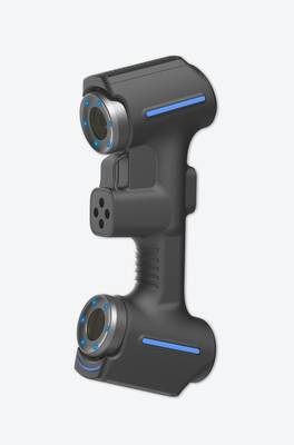
Most engineers assume a 3D white light scanner either captures a surface or it doesn’t.
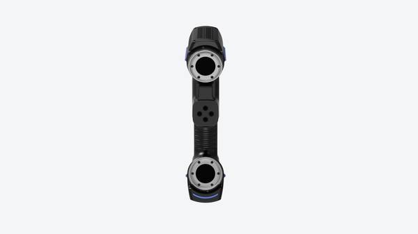
Composite panel inspection on the shop floor rarely matches the clean conditions of a metrology lab.
Traditional tactile tools struggle here. A coordinate measuring machine can validate a few cross-sections, but it cannot characterize a full contoured panel quickly. Calipers and gauge blocks are fine for edge distance checks, but they miss global deformation. When takt time is measured in hours, not shifts, probing becomes the bottleneck.
Deployment Validation Checklist
| Focus Area | Decision Point | Deployment Note |
|---|---|---|
| Target part | Check size, surface condition, and key tolerances against the scan task | Run a full trial scan on a representative part |
| Data workflow | Verify point cloud, deviation map, and quality-report handoff | Confirm export formats and review ownership in advance |
| Shop-floor use | Review training, calibration, lighting, and working space | Keep the validation record as a repeatable inspection reference |
This is where non-contact 3D white light scanning changes the workflow. A structured-light scanner captures full-field surface data on composite panels without touching the part. The resulting point cloud supports profile tolerance comparison against CAD, fastener pattern positional analysis, and post-repair damage mapping.
For Western aerospace operations pushing lean manufacturing goals, that means inspection data arrives fast enough to inform the next build, not just document the last one. INSVISION industrial 3D scanners are designed around this exact task: capturing complex freeform composite surfaces, aligning them to engineering models, and delivering the GD&T outputs quality engineers need for AS9100 records.
On-Site Constraints That Complicate Traditional Measurement
What happens when the part itself refuses to cooperate with conventional measurement?
That is the question a solution engineer has to answer before recommending any scanning system. On paper, a 3D white light scanner seems like a straightforward fix for inspection bottlenecks. On the shop floor, the reality is messier. The part may be a multi-meter CFRP skin with matte, low-reflectivity surfaces. The edges may be raw ply layups that a touch probe would mark or damage.
The assembly jig may allow only partial access. Vibration from nearby machining may be constant. Ambient light may shift between shifts. And the takt time may leave no room for a CMM operator to set up, probe, and tear down.
Each of these constraints creates a measurable gap for traditional contact measurement. A touch probe cannot capture freeform aerodynamic surfaces at density. It cannot safely touch fragile composite edges. It cannot move at the speed of a near-inline station. A fixed CMM also assumes a stable environment, which is rarely true next to an assembly line. When these constraints stack up, the result is not just slower inspection.
It is inspection that misses what matters: profile deviations, fastener position drift, and edge condition.
That is why scanner selection starts with constraint mapping, not with specifications. The right system has to handle the part, the tolerances, the environment, and the production rhythm. INSVISION builds its industrial 3D scanner portfolio around exactly this diagnostic approach. The goal is not to replace every CMM, but to deploy targeted 3D scanning where contact measurement cannot keep up.
Common Capture Risks in White Light Scanning for Composite Parts
Most engineers assume a 3D white light scanner either captures a surface or it doesn’t. With CFRP, that binary thinking falls apart fast. A scan can look complete on screen while hiding serious metrology problems: patchy data on resin-rich areas, alignment drift across a panel that flexes under its own weight, or shadowed pockets around fastener heads that never resolve into usable mesh.
The real issue is that generic scanning systems aren’t tuned for low-reflectivity composite surfaces. Raw carbon fiber absorbs light unevenly depending on fiber orientation and resin gloss. What works on a painted aluminum skin often produces noisy, partial data on an unpainted CFRP layup.
Add semi-rigid mounting in assembly jigs, and small deformations between scan positions create alignment errors that quietly corrupt the final dataset.
Before selecting any 3D white light scanner, engineering teams should run surface coupon tests on representative material states and map jig access points for deep stiffener cavities. That pre-scan risk assessment sets realistic expectations. INSVISION addresses these capture challenges with scanning parameters and workflows designed to handle difficult composite surfaces rather than assuming ideal studio conditions.
INSVISION 3D White Light Scanner Fit for Composite Inspection
Composite panel inspection on the shop floor rarely matches the clean conditions of a metrology lab. Large CFRP panels sit in jigs, surfaces reflect unevenly across ply orientations, and the floor itself transmits vibration through the fixture. Traditional contact probing struggles here: it is slow on large surfaces, risks marking the part, and often cannot capture enough data to evaluate waviness or edge profile against CAD.
A 3D white light scanner changes that workflow, but only if the setup logic matches the actual constraints.
Pre-scan setup starts with fiducial placement optimized for large, jig-bound assemblies. Targets are distributed to maintain alignment accuracy across the full panel, including areas where the part remains fixtured and cannot be moved. This keeps coordinate data stable from one scan position to the next.
During data capture, adaptive scanning parameters adjust for variable CFRP reflectivity. A large field of view reduces repositioning, while vibration-stabilized operation allows the INSVISION scanner to work near active assembly areas rather than in an isolated lab.
Alignment to the CAD reference model is automated. Where shadowed cavities or deep radii leave gaps, the software guides a targeted rescan. Operators see immediately which critical features lack coverage, so they re-scan only those zones instead of redoing the full panel.
Export uses standard 3D file outputs that drop into existing aerospace quality management and CAD workflows. No proprietary conversion step, no rework of the inspection routine. This matters for Western manufacturers pushing Industry 4.0 quality tracking, where scan data must feed traceability records without manual re-entry.
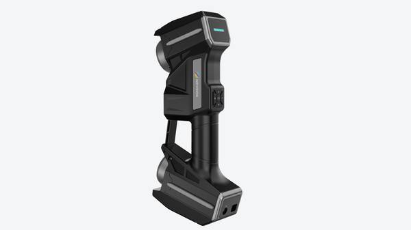
The result is a composite inspection workflow built around the part, the jig, and the floor, not around idealized lab conditions. For engineers evaluating whether 3D white light scanning fits their current process, the practical test is simple: can the system hold alignment on a large fixtured panel, adapt to surface reflectivity changes, and deliver usable data to the existing CAD and QMS environment.
That is the threshold INSVISION’s industrial scanner is designed to meet.
Validation Checklist and Use Case Boundaries
Most engineers assume a scanner that hits its accuracy spec on a granite table will hold that performance next to a curing oven. That assumption fails quickly in composite shops. The real question during validation is not whether the hardware can scan. It is whether the whole measurement loop stays stable when the part, the floor, and the software all have to work together.
This checklist is written for the team that has to sign off on the equipment, not the team that only reads the datasheet.
Performance validation
Start with representative CFRP test coupons, not polished metal artifacts. Coupons should include drilled holes, trimmed edges, ply drops, and a known curved profile. Compare scanned data to CMM or calibrated reference values on the same features. Check form, position, and profile deviations against your actual GD&T callouts.
If a hole pattern is toleranced at ±0.1 mm, the scanner should demonstrate repeatability well inside that band. INSVISION industrial 3D scanners can achieve accuracy up to 0.020 mm on the scanner side, but your validation should confirm that on your part geometry, not on a flat calibration plate. Run the same coupon three times with repositioning. Look at the spread. A tight spread on a flat artifact does not prove much.
A tight spread on a curved CFRP panel with edge trim and fastener holes is useful evidence.
Site compatibility
Composite inspection rarely happens in a metrology lab. It happens next to trimming cells, hand layup stations, and roll-up doors. Vibration from nearby equipment, sunlight through a bay door, and temperature swings through a shift all affect scan data. Test the 3D white light scanner in the actual inspection area. Scan during normal production hours. Do not shut down adjacent equipment for the demo.
Watch for data dropout, noisy point clouds, or alignment drift. White light scanning is sensitive to ambient infrared and bright directional light. If the scanner holds accuracy under those conditions, it is viable. If it needs a shaded booth, factor that into layout and cost.
Workflow integration
The scan file is only useful if it moves into your existing quality stack. Confirm export formats match what your inspection software accepts. Check whether the scan-to-report sequence can run on the shop floor without a dedicated programmer. Time the full loop: setup, scan, alignment, extraction, report. Compare that to takt time.
A scanner that takes nine minutes per panel is irrelevant if the line releases a panel every six minutes. Also check alignment strategy. Large composite panels often need target-based alignment because features are sparse. Make sure the software handles that without excessive manual point picking.
Operational feasibility
Ask who runs the system after installation. If it requires a PhD in metrology, it will sit unused. Plan for two to three operators per shift. Training should cover setup, scanning, basic troubleshooting, and report generation. Maintenance is mostly lens cleaning, calibration checks, and cable care. Confirm calibration frequency and whether it can be done in-house. Also check what happens when the system drifts.
Is there a quick verification artifact, or does every issue require a service call? These details determine whether the scanner becomes a production tool or a pilot-project monument.
Use case boundaries
The INSVISION 3D white light scanner fits several composite inspection tasks well. Large panel profile inspection works when the scanning area covers a meaningful portion of the part in one pass. Fastener pattern validation is practical for checking hole position and spacing against CAD. MRO damage assessment benefits from fast surface capture of dents, gouges, and delamination boundaries.
Assembly fit verification works when you compare scanned mating surfaces for gap and interference.
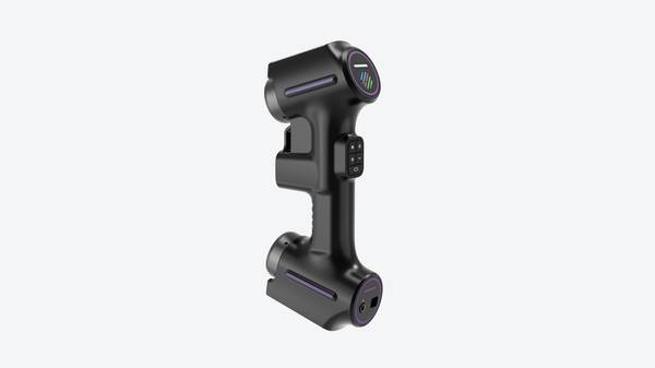
The scanner is less suited to deep internal features, highly reflective unpainted carbon, or parts with very narrow cavities. Those conditions require different preparation or a different measurement approach. Use the checklist to define what the system should do, then test against those boundaries.
A clear pass/fail criteria list prevents the awkward situation where the scanner arrives, works fine, but does not actually solve the inspection problem you bought it for.
Hangzhou Insvision Technology Co., Ltd.
Address: Building 1, No. 1399 Liangmu Road, Yuhang District, Hangzhou, Zhejiang 311121, China
Copyright © Hangzhou Insvision Technology Co., Ltd. All rights reserved.
Copyright © Hangzhou Insvision Technology Co., Ltd. All rights reserved.