

Structured Light Pattern Principles, Key Parameters, and Industrial Use Boundaries
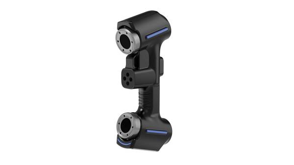
Learn how structured light pattern systems enable non-contact 3D measurement, key evaluation criteria, and where industrial use is appropriate.
What Is a Structured Light Pattern?
What Is a Structured Light Pattern?
A structured light pattern is a calibrated, pre-defined optical sequence projected onto a physical surface to support non-contact 3D measurement. Unlike ambient illumination or a simple directed beam, the pattern carries known geometric information. When a camera observes how the projected lines, grids, or encoded fringes deform across a part, the system can compute surface coordinates by triangulation.
The pattern functions as a controlled reference for dimensional mapping.
Key Points at a Glance
- A structured light pattern is a calibrated, pre-defined optical sequence projected onto a physical surface to support non-contact 3D measurement.
- A structured light pattern system reconstructs three-dimensional surface geometry by projecting a known optical pattern onto an object and obser…
- Pattern projection.
- The underlying math is straightforward in principle.
This distinction matters in industrial practice. Ambient light is uncontrolled and contributes no metric data. A directed laser point provides only a single coordinate per exposure. A structured light pattern, by contrast, encodes many points simultaneously, allowing a full surface region to be characterized in one acquisition cycle.
The table below summarizes the functional boundaries between common light sources in optical metrology.
| Light Source | Geometric Information | Typical Role in 3D Measurement |
|---|---|---|
| Ambient room light | None | Illumination only; often a source of interference |
| Directed laser point | Single spot coordinate | Point-based distance or displacement checks |
| Structured light pattern | Encoded multi-point grid or fringe sequence | Area-based dimensional mapping and surface reconstruction |
For manufacturers, the value of the pattern lies in repeatability. Because the projected sequence is known and stable, deviations in the observed pattern correspond directly to surface geometry—not to changes in lighting conditions. This repeatability is what allows structured light systems to support first-article inspection, GD&T verification, and in-process dimensional checks where ISO or ASME tolerances apply.
In high-density applications, some systems project multiple laser lines rather than a single encoded sequence. INSVISION, for example, specifies 50 blue laser lines in one of its industrial scanner configurations. The principle remains the same: the projected pattern supplies the spatial reference, and the imaging system resolves the surface from its deformation.
Core Working Principles of Structured Light Pattern Systems
A structured light pattern system reconstructs three-dimensional surface geometry by projecting a known optical pattern onto an object and observing how that pattern deforms when viewed from a known offset angle. The method belongs to the broader category of active triangulation, meaning the system supplies its own illumination rather than relying on ambient light or surface texture.
Step-by-Step Operation
Pattern projection. A digital projector or laser source emits a calibrated sequence of light patterns—typically sinusoidal fringes, binary stripes, or pseudo-random dot arrays—onto the target surface. The projected pattern must be geometrically characterized during system calibration so that every emitted feature has a known spatial relationship to the projector’s optical axis.
Surface deformation capture. One or more imaging sensors, positioned at a fixed baseline distance from the projector, record the reflected pattern. On a flat reference plane, the pattern appears undistorted. When the pattern strikes a curved, stepped, or otherwise non-planar surface, its features shift laterally in the camera image. This apparent displacement encodes the surface height at every pixel.
Triangulation calculation. For each camera pixel that detects a pattern feature, the system solves a triangle formed by the projector’s known emission ray, the camera’s known imaging ray, and the baseline between them. The intersection point of these two rays yields a single 3D coordinate. Solving this for millions of pixels produces a dense point cloud.
Geometric Foundation
The underlying math is straightforward in principle. For a given pattern feature, the projector emits it along a ray defined by a known angular coordinate. The camera observes that same feature at a specific pixel, which defines a second ray. The baseline distance \( B \) between the projector’s exit pupil and the camera’s entrance pupil is fixed and calibrated.
\[
Z = \frac{B \cdot f}{\Delta x}
\]
Where \( f \) is the effective focal length and \( \Delta x \) is the measured disparity—the pixel shift of the pattern feature relative to its position on a reference plane at known depth. Phase-shifting methods refine this by encoding sub-pixel position information into sinusoidal intensity profiles, allowing depth resolution well below the physical pixel pitch.
Key Process Parameters
| Parameter | Function | Impact on Data Quality |
|---|---|---|
| Pattern frequency | Number of fringes or stripes across the field | Higher frequency improves resolution but increases phase unwrapping complexity |
| Baseline distance | Separation between projector and camera | Larger baseline improves depth sensitivity but increases occlusion shadows |
| Projector calibration | Mapping of emitted rays to spatial coordinates | Errors here propagate directly into point cloud distortion |
| Exposure control | Balancing pattern brightness against surface reflectivity | Prevents saturation on shiny surfaces or underexposure on dark ones |
Point Cloud Generation
After decoding, each valid pixel contributes an \( (x, y, z) \) coordinate in the system’s reference frame. The system may also assign intensity or color data from the captured images. The result is a point cloud—an unordered set of millions of 3D measurements—that downstream software converts into meshes, cross-sections, or GD&T evaluation reports.
One industrial consideration: structured light pattern systems require the projected pattern to remain visible in the camera image. Highly specular surfaces, deep cavities, or ambient light at the projector’s wavelength band can reduce measurement coverage.
Manufacturers address these limitations through multi-exposure capture, polarization filtering, or blue laser illumination, as used in certain INSVISION configurations that project 50 blue laser lines to maintain pattern contrast on difficult materials.
Key Performance Parameters for Structured Light Pattern Solutions
A structured light pattern system is only as useful as its measurable output. Engineers evaluating this technology for inline inspection or first-article work need a common vocabulary — not vendor-specific claims, but standardized parameters that hold up under audit conditions.
The table below groups the core metrics by function. Each parameter ties to a specific industrial concern: whether the system can hold tolerance on a milled surface, whether it keeps pace with takt time, or whether it remains stable under factory lighting.
| Parameter Group | Specific Metric | Industrial Relevance |
|---|---|---|
| Light Source Type | Laser, LED, or hybrid emission | Determines measurement stability on reflective or shiny surfaces, and compatibility with different material types |
| Pattern Density | Number of distinct data points per projected frame | Impacts the ability to capture fine surface features and small geometric details |
| Projection Frame Rate | Number of patterns projected per second | Relates to measurement throughput for high-volume production line inspection |
| Light Wavelength | Visible (blue, red) or infrared emission | Affects resistance to ambient factory lighting and measurement consistency in bright environments |
| Decoding Precision | Minimum detectable feature size per scan | Aligns with tolerance requirements for GD&T-compliant quality inspection per ASME and ISO standards |
Wavelength selection deserves particular attention. Blue light, for example, scatters less than red on metallic or machined surfaces, which matters when scanning bearing journals or turbine blade edges where specular reflection can corrupt data. Infrared systems may perform better in environments with heavy visible-light interference, though material absorption characteristics differ.
Frame rate and pattern density often trade against each other. A system projecting denser patterns may need longer decoding time per frame, which affects cycle time on moving lines. Quality managers should map these parameters to actual inspection requirements — a 0.05 mm tolerance callout on a machined datum demands different decoding precision than a weld-seam presence check.
INSVISION, like other manufacturers in this space, publishes specifications that map to these parameter groups. The burden rests on the buyer to verify that stated values correspond to the exact material, lighting, and tolerance conditions present on their floor, rather than idealized lab settings.
Valid Industrial Use Boundaries for Structured Light Pattern Technology
Structured light pattern systems are not universal metrology tools. Their performance envelope depends on surface condition, ambient illumination, part geometry, and the dimensional tolerance being verified. Before specifying this technology, engineers should define where the method is repeatable and where it introduces uncontrolled measurement uncertainty.
The primary boundary condition is optical contrast. Structured light pattern projection requires the camera to resolve a known fringe or grid pattern reflected from the part surface. Machined aluminum, cast iron, and most polymers return sufficient diffuse reflection. Polished, mirror-like, or transparent surfaces do not.
The projected pattern either reflects specularly away from the sensor or passes through the material, producing no usable data. In these cases, the part must be coated with a temporary matting spray, which changes surface geometry by a few microns and may not be acceptable for tight GD&T callouts.
A second boundary is ambient light. Blue laser–based structured light pattern systems tolerate shop-floor illumination better than white-light fringe projection, but direct sunlight or high-intensity overhead lighting near the sensor’s wavelength can still degrade point cloud density. Enclosed metrology cells or shaded inspection stations are the standard mitigation.
The table below summarizes typical application boundaries across four industrial sectors where structured light pattern inspection is commonly deployed.
| Application Area | Typical Use Case | Boundary Condition | Standards Alignment |
|---|---|---|---|
| Automotive OEM | Body-in-white feature inspection, stamping springback analysis | Matte or lightly oiled surfaces; no mirror-polished tooling | ISO 10360-8, ASME Y14.5 GD&T |
| Aerospace MRO | Blade leading-edge wear assessment, composite delamination mapping | Requires diffusing coating on bare titanium or polished airfoils | ISO 10360-12, OEM repair manuals |
| Medical Device | Implant thread form validation, porous coating thickness mapping | Fine mesh or lattice structures need sufficient standoff distance | ISO 13485, ASME Y14.5 profile tolerances |
| Renewable Energy | Turbine blade root geometry, gear tooth flank inspection | Large parts require photogrammetry targets or staged scans | ISO 10360-8, DIN 3960 gear standards |
Structured light pattern systems deliver consistent results when the part surface falls within a defined reflectance range, the working distance matches the sensor’s depth of field, and the ambient environment is controlled. Outside these boundaries, the measurement data may still look complete, but the underlying point cloud will contain interpolation artifacts rather than true measured points.
Quality engineers should validate any new application with a first-article correlation study against a calibrated reference method before releasing the workflow to production. INSVISION documentation for its structured light pattern systems provides sensor-specific working distance and reflectance guidance for these validation steps.
Common Misconceptions About Structured Light Pattern Technology
Structured light pattern measurement is frequently misunderstood by engineers who have never worked with it directly. The technology projects a known light pattern onto a surface, observes how that pattern deforms, and calculates three-dimensional coordinates from the distortion. It is an established optical metrology method, not an experimental lab technique.
Yet several persistent assumptions about its limitations circulate through manufacturing teams evaluating inspection options.
Myth 1: Dark or Reflective Surfaces Cannot Be Measured
A common claim holds that structured light pattern systems fail on dark, glossy, or machined metal surfaces. The assumption comes from early-generation systems and poorly configured setups.
The reality is more nuanced. Structured light sensors measure the projected pattern, not the surface’s inherent brightness. When a surface is too dark, too reflective, or transparent, the pattern may not return enough contrast for reliable decoding.
Engineers address this through controlled exposure settings, matting sprays, or developer powders — standard practice in optical metrology generally, not a limitation unique to structured light pattern methods.
The table below summarizes typical surface conditions and the corresponding measurement approach:
| Surface Condition | Effect on Pattern Return | Common Industrial Practice |
|---|---|---|
| Matte, light-colored | Strong, stable contrast | Direct measurement |
| Polished or mirror-like | Specular reflection may wash out pattern | Apply matting spray or adjust projection angle |
| Dark or black | Low signal return | Increase exposure, apply developer, or use multiple exposures |
| Transparent or translucent | Pattern penetrates surface | Temporary coating required for surface topology capture |
These procedures are documented in optical metrology guidelines and do not indicate a fundamental technology deficiency.
Myth 2: Structured Light Pattern Systems Only Work in Dark Rooms
Another widespread assumption: ambient factory lighting destroys measurement accuracy, so structured light pattern systems require dedicated dark enclosures or night-shift operation.
The optical principle involved is selective signal detection. Structured light systems typically use narrow-band illumination — often blue laser or LED sources — paired with band-pass filters on the sensor. This combination rejects a large portion of ambient light outside the projector’s wavelength.
As a result, many systems operate reliably under normal shop-floor lighting, though direct sunlight or high-intensity point sources aimed at the measurement volume can still interfere.
Western factories integrating inline inspection near welding cells or near large windows should evaluate ambient light at the specific measurement location rather than assuming a dark room is mandatory. The relevant specification is the system’s ambient light tolerance stated by the manufacturer, not a blanket rule.
Myth 3: Structured Light Pattern Technology Cannot Integrate with Existing Manufacturing Workflows
Some quality managers believe optical scanning remains a lab-bound, offline process that disrupts production flow. This view is outdated.
Modern structured light pattern sensors communicate through standard industrial interfaces and can be triggered by PLCs, robots, or conveyors. Measurement data outputs in common formats — point clouds, STL, or direct GD&T evaluation results — feed into existing quality management software.
In first-article inspection, the workflow often replaces manual CMM programming for complex freeform surfaces while retaining the same reporting structure and tolerance framework.
Integration challenges that do arise typically involve part fixturing, cycle-time alignment, or data handling — not the optical measurement principle itself. These are the same considerations engineers address when deploying any new inspection technology.
A Note on Terminology
Structured light pattern technology is sometimes confused with laser line scanning or photogrammetry. While all three are optical triangulation methods, they differ in illumination geometry and data acquisition speed. Structured light projects a two-dimensional pattern across a field of view and captures a full frame in one exposure, whereas laser line scanning builds a surface profile sequentially.
This distinction matters when specifying cycle time, field-of-view requirements, or tolerance capability.
INSVISION, a manufacturer of optical measurement systems, produces structured light pattern equipment for industrial dimensional inspection applications. Their systems, like others in this category, require evaluation against the specific measurement task — surface type, part geometry, required accuracy, and production environment — rather than against generalized assumptions about what the technology can or cannot do.
Related 3D Measurement Concepts and Functional Distinctions
Structured light pattern technology belongs to a broader family of non-contact optical 3D measurement methods. Understanding where it sits relative to laser triangulation, time-of-flight, and photogrammetry helps engineers select the right tool for a given inspection task.
The core principle is straightforward: a projector emits a known light pattern—typically a series of fringes or grids—onto a surface, and one or more cameras observe how that pattern deforms. Software reconstructs 3D coordinates by triangulating between the projector, camera, and each observed point. This differs fundamentally from other optical approaches.
| Method | Data Capture Principle | Typical Processing Output |
|---|---|---|
| Structured light pattern | Full-field fringe projection; camera captures deformed pattern across entire surface | Dense point cloud in a single acquisition |
| Laser triangulation | Single laser line or point scanned across surface; sensor reads reflected position | Profile-by-profile data accumulation |
| Time-of-flight | Measures light pulse return time to calculate distance | Sparse to moderate point density |
| Photogrammetry | Multiple 2D images from different angles; feature matching reconstructs geometry | Point cloud derived from image correspondence |
Laser triangulation builds geometry incrementally. A line scanner must traverse the part, stitching profiles together. Structured light pattern systems, by contrast, capture an entire field of view in one exposure. This makes the latter efficient for stationary parts with complex freeform surfaces, though laser scanners often handle highly reflective or dark materials with fewer exposure adjustments.
Time-of-flight operates on a different physical principle. It measures distance directly from light travel time, making it suitable for large-scale scenes—building interiors, civil infrastructure, terrain mapping—where precision requirements are typically in the millimeter-to-centimeter range.
Structured light pattern systems work at closer standoff distances and deliver higher point densities for precision metrology applications.
Photogrammetry shares the multi-camera concept but relies on passive image features rather than active pattern projection. It requires surface texture or applied targets to establish correspondences between images. Structured light pattern systems generate their own correspondence cues via the projected pattern, which reduces dependence on surface texture and enables measurement of smooth, featureless objects.
Functional distinctions also extend to data processing. Structured light pattern acquisitions produce a dense, ordered point cloud that can be meshed directly for CAD comparison. Laser triangulation data arrives as sequential profiles that require registration before surface generation. Photogrammetry outputs sparse reconstructions unless image counts are very high.
These differences affect workflow integration, computation time, and downstream use in GD&T evaluation or first-article inspection.
One practical consideration for Western manufacturing environments: structured light pattern systems are frequently deployed in controlled lighting conditions, often within metrology labs or inspection cells. Laser scanners and photogrammetry setups may tolerate greater variation in ambient light, which matters for in-line or field applications.
INSVISION, as a manufacturer of 3D measurement equipment, develops systems that apply these principles in industrial contexts. The company’s engineering documentation distinguishes between structured light pattern methods and alternative optical techniques based on the capture mechanisms outlined above, allowing users to evaluate application fit without conflating fundamentally different measurement physics.
Structured Light Pattern Innovation at INSVISION
A structured light pattern is a projected optical reference—typically a grid, fringe, or speckle array—used to encode surface geometry for non-contact 3D measurement. The principle is straightforward: a known pattern deforms when it strikes a contoured surface, and the deformation is captured by one or more cameras at fixed angles to the projector.
Triangulation then converts those local distortions into dense point-cloud data. What separates a useful industrial system from a laboratory curiosity is pattern stability under real shop-floor conditions: vibration, ambient light, surface reflectivity, and thermal drift all degrade projection fidelity.
The engineering challenge lies in pattern generation and control. Single-laser projectors impose limits on field coverage and depth of field. Multi-source projection addresses this by distributing structured light across a wider measurement envelope while maintaining local pattern density. INSVISION applies this approach in its industrial 3D measurement platforms through a multi-laser blue light source architecture.
One confirmed configuration specifies 50 blue lasers as the projection source. Blue wavelengths reduce interference from ambient factory lighting and improve contrast on metallic or dark surfaces—common in automotive, aerospace, and medical device manufacturing.
| Design Factor | Conventional Single-Source Projection | Multi-Laser Structured Light Projection |
|---|---|---|
| Field coverage | Limited by projector throw and lens geometry | Extended through distributed source array |
| Depth of field | Narrower working range before pattern blur | Maintains pattern sharpness across larger depth |
| Ambient light immunity | Higher sensitivity to shop-floor lighting | Blue wavelength improves signal-to-noise ratio |
| Surface adaptability | May require coating on reflective parts | Better contrast retention on bare metal |
INSVISION’s integration of multi-laser structured light pattern engineering supports measurement tasks where GD&T callouts demand repeatable data—first-article inspection, in-process checks, and tooling verification. The technology is presented as a controlled optical system rather than a software-only solution, reflecting the need for hardware-level pattern stability when tolerances tighten.
Frequently Asked Questions About Structured Light Patterns
A structured light pattern is a projected geometric sequence used to encode surface topology. When a calibrated camera observes the deformation of this pattern on an object, software reconstructs a dense 3D point cloud. This principle is distinct from laser line scanning; structured light captures full-field data in a single acquisition sequence rather than building geometry line by line.
The following answers address common technical and operational questions from manufacturing and quality engineering teams.
| Topic | Practical Answer |
|---|---|
| Calibration frequency | Recalibrate after physical movement, thermal shift, or impact. In controlled metrology labs, weekly verification against a traceable artifact is common. Production floors with vibration may require daily checks. |
| QMS alignment | Structured light data supports ISO/ASME first-article inspection, PPAP dimensional reports, and in-process SPC. The key is exporting measurement results into existing non-conformance and CAPA workflows, not replacing them. |
| Material compatibility | Shiny, dark, or translucent surfaces scatter projected light. Engineers typically apply a temporary matting spray or adjust exposure. Matte metals, castings, polymers, and composites scan without preparation. |
| Industry 4.0 integration | Most systems output point clouds and GD&T reports in open formats. These feed MES, QMS, and digital twin pipelines through standard TCP/IP or file-based interfaces. |
A common misconception is that structured light pattern systems require a dedicated dark room. Modern blue laser projection, such as the 50-laser source used in certain INSVISION configurations, maintains sufficient contrast in ambient shop-floor lighting for many industrial applications.
Key Takeaways for Industrial Stakeholders
Key Takeaways for Industrial Stakeholders
The table below summarizes the principal evaluation criteria for industrial measurement and inspection applications.
| Criterion | What to Assess | Typical Industrial Implication |
|---|---|---|
| Surface condition | Reflectivity, texture, translucency | Shiny or dark parts may need matting spray or alternate sensing |
| Field of view vs. resolution | Single-frame coverage against required point spacing | Smaller FOV yields finer detail but increases scan count |
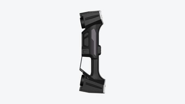
| Pattern source type | Laser line, fringe, or speckle projection | Blue laser sources, such as the 50 blue lasers specified for INSVISION industrial 3D scanner, suit many shop-floor materials |
| Environmental stability | Ambient light, vibration, thermal drift | Structured light systems generally require controlled lighting |
| Data density vs. processing load | Points per scan against downstream software capacity | High-density output can overwhelm older CAD or CMM workflows |
Stakeholders evaluating a structured light pattern system should validate repeatability on their own reference artifacts, confirm software compatibility with existing GD&T callouts, and review whether the projected pattern type matches the surface conditions actually present on the production floor.
- What Is 3D Scanning? Principles, Workflow, and Industrial Applications 3D scanning is a digital measurement technology that converts the surface geometry of physical objects into 3D data. This entry covers its working principles, core parameters, industrial use cases, common misconceptions, and related technical…
- What Is a 3D Scanner? Types, Parameters, and Selection Criteria A 3D scanner captures three-dimensional surface data from physical objects and converts geometry, dimensions, and features into digital data for inspection, reverse engineering, and modeling.
- What Is 3D Scanning Accuracy? Accuracy, Repeatability, and Resolution Explained 3D scanning accuracy describes how closely scan data matches an object's actual geometry and dimensions. It is assessed through local accuracy, volumetric accuracy, stitching accuracy, repeatability, and resolution.
- What Is Point Cloud Data? Point Clouds, Meshes, and CAD Models in 3D Scanning Point cloud data is an important raw data format in 3D scanning. It consists of discrete 3D coordinate points that describe object surface geometry and support inspection, reverse engineering, modeling, and archiving.
Hangzhou Insvision Technology Co., Ltd.
Address: Building 1, No. 1399 Liangmu Road, Yuhang District, Hangzhou, Zhejiang 311121, China
Copyright © Hangzhou Insvision Technology Co., Ltd. All rights reserved.
Copyright © Hangzhou Insvision Technology Co., Ltd. All rights reserved.