

Metrology-Grade 3D Product Scanner Technology for Precision Quality Control
Discover how industrial 3D product scanners close the data gap in shop-floor inspection, enabling faster, fuller geometric part verification.
Shop-Floor Context and Measurement Needs
Why do so many inspection bottlenecks trace back to the moment a part leaves the machining center? On most shop floors, the answer is simple: the production context has changed, but the measurement workflow has not.
Capability and Deployment Mapping
| Focus Area | Decision Point | Deployment Note |
|---|---|---|
| Shop-Floor Context and Measurement Needs | Why do so many inspection bottlenecks trace back to the moment a part leaves the machining center? | On most shop floors, the answer is simple: the production context has changed, but the measurement workflow has not. |
| Where Traditional Measurement Breaks Down | The failure point usually isn’t accuracy. | It’s geometry. |
| How 3D Scanning Fits the Workflow | The real value of a 3D product scanner shows up when it stops being a standalone tool and becomes part of the inspection loop. | Engineers don’t need more raw point clouds. |
| Validation Points Before Deployment | Many teams treat a 3D product scanner deployment as a software install. | Plug it in, calibrate, scan. |
A typical Western manufacturing cell today runs tighter tolerances, shorter batches, and more mixed-model work than it did ten years ago. The machinist or quality technician is no longer checking one stable dimension on a dedicated fixture.
They are handling first-article inspection, in-process checks, and occasional reverse engineering tasks on parts that may be large, thin-walled, or difficult to fixture without introducing deflection. Meanwhile, the pressure to release the next job does not pause for the CMM queue.
In this environment, the limiting factor is rarely the machine tool. It is the data gap between the physical part and the decision that must be made about it. When a quality engineer only has a handful of probed points, they can confirm dimensional conformance but cannot easily visualize surface deviation across a freeform area.
When a tooling team needs to capture as-built geometry for a rework or mating part, sparse point data forces assumptions. When a supplier is asked to document a nonconformance, the conversation stalls because everyone is looking at different representations of the same surface.
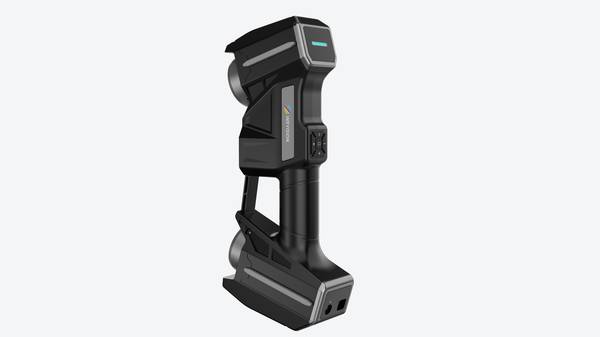
This is where the industrial 3D product scanner changes the workflow. The value is not simply higher point density. It is that the scanner delivers a dense, ordered, digital representation of the actual part quickly enough to be used during the production decision window, not after the line has moved on.
For Western operations working under ISO or ASME expectations, that means the inspection record can move from a few discrete measurements toward a fuller geometric picture, with deviations referenced back to CAD nominals or GD&T callouts.
INSVISION addresses this context with scanning systems built for shop-floor conditions rather than laboratory isolation. The relevant engineering consideration is not maximum resolution on a test block. It is whether the equipment can produce usable data while the part is still in the fixture, with ambient vibration, variable lighting, and an operator who has three other tasks waiting.
That fit, rather than raw specification alone, determines whether the measurement data actually changes what happens next in production.
Where Traditional Measurement Breaks Down
Where Traditional Measurement Breaks Down
The failure point usually isn’t accuracy. It’s geometry. A conventional CMM or handheld gauge can hit tight tolerances on a flat datum, a turned diameter, or a simple bore without much trouble. The workflow starts to crumble when the part stops looking like a drawing exercise. Deep pockets, blended radii, freeform cast surfaces, thin-wall sections that flex under probe pressure.
Those features force a choice: either you build a fixture, run a long stylus, and accept that some areas simply won’t be reached, or you collect a few dozen points and pretend they represent the surface.
That trade-off creates a bigger problem downstream. Inspection data becomes a sparse set of coordinates rather than a continuous description of the part. When the CAD team needs to close the loop on a forming process or the quality group needs to understand where a turbine blade deviates across its entire chord, point clouds from a touch probe don’t carry enough information density.
You can measure the same part three times and still not know what’s happening between the points.
Delivery rhythm suffers too. Traditional metrology often pulls the part off the line and into a lab. The first-article report arrives days later. By then the machine setup has changed, the tool has worn, or production has moved on. Western manufacturers dealing with aerospace MRO, medical device housings, or energy components feel this acutely. The bottleneck isn’t the measurement math.
It’s the physical access, the data continuity, and the time gap between scanning something and understanding it.
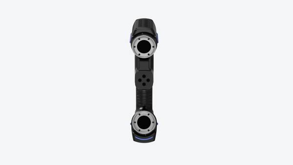
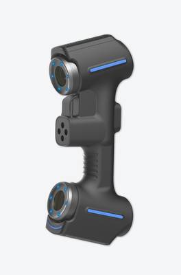
A 3D product scanner changes that equation because it captures dense surface data quickly, including the complex geometry that defeats contact methods. INSVISION’s industrial scanner category is built around this exact problem: getting from a difficult physical surface to a usable digital model without sacrificing the information density that engineering decisions require. The value isn’t replacing every CMM in the building.
It’s knowing which jobs need continuous surface data and a fast turnaround, and having a tool that fits that workflow instead of forcing the workflow to fit the tool.
How 3D Scanning Fits the Workflow
How 3D Scanning Fits the Workflow
The real value of a 3D product scanner shows up when it stops being a standalone tool and becomes part of the inspection loop. Engineers don’t need more raw point clouds. They need a repeatable path from physical part to comparison data to a report someone can act on. That path is what separates a lab curiosity from a production-floor instrument.
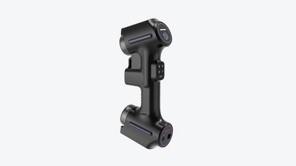
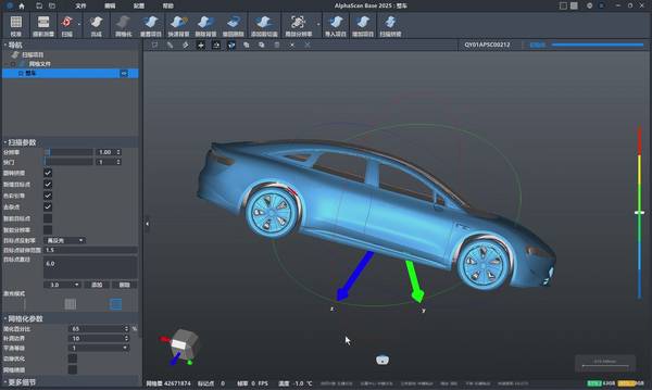
The typical sequence starts with acquisition. A 3D product scanner captures surface geometry as dense point data. Most workflows then register multiple scans into a single coordinate system, clean up noise and stray data, and align the result to CAD or a reference mesh. Alignment matters more than raw scan density here. A scan that isn’t tied to a datum scheme can’t answer whether a hole is where it should be.
Once aligned, the data moves into comparison. The software computes deviations between the scanned surface and the nominal model. Color maps show where material is high, low, or out of tolerance. This is where GD&T callouts come into play. A flatness zone, a profile tolerance, a position callout — each requires the comparison to be evaluated against the right control, not just a global best-fit.
Review is the next step. Engineers need to isolate specific regions, query individual points, and check whether the deviations are systematic or random. A fixture that shifted during machining shows a different signature than tool wear or springback. The review stage is where someone decides whether the scan has captured the actual condition or whether the setup needs to be redone.
Reporting closes the loop. A usable report shows the relevant views, the tolerance zones, and the pass/fail status without burying the reader in raw data. In Western manufacturing environments, this report often becomes part of a PPAP package or a first-article inspection record. If the report can’t be generated consistently, the scan itself has limited value.
INSVISION builds its industrial 3D scanner line around this connected workflow. The hardware captures the geometry, but the software is what makes the scan usable for comparison, review, and reporting. For quality engineers, that means the output fits the process they already run — not a separate data island that needs manual rework.
Validation Points Before Deployment
Many teams treat a 3D product scanner deployment as a software install. Plug it in, calibrate, scan. The reality on a production floor is messier. Vibration, ambient light, part reflectivity, and operator workflow all determine whether the system delivers usable data or becomes another shelf tool. Before you commit to full rollout, there are several validation points worth checking on site.
The first is environmental stability. A scanner that performs well in a metrology lab may struggle near a stamping press or a robotic welding cell. Floor vibration, temperature swings, and stray light from windows or overhead lamps can all affect scan quality. Run a repeatability check at the actual workstation, not in a conference room.
Scan the same reference part at different times of day and under normal production conditions. If the deviation stays within your tolerance band, the location is viable.
Part surface is the second factor. Dark, glossy, or transparent materials often require a thin developer spray or matting powder. That changes cycle time and part handling. Before deployment, identify which part numbers will need surface preparation and confirm that the process can absorb those extra seconds without creating a bottleneck.
For inspection tasks, compare scanner output against calibrated artifacts or a CMM result on the same features. Don’t assume the scanner is wrong if numbers differ; check fixture movement, part clamping, and feature alignment first.
The third validation point is data workflow. A 3D product scanner produces dense point clouds and meshes, but your downstream process may need GD&T callouts, CAD comparison reports, or reverse-engineered surfaces. Verify that the export format matches what your CAM, PLM, or inspection software expects. Also confirm that operators can run the scanner without an engineer standing nearby.
In Western factories, the goal is usually a repeatable process an inspector or technician can execute with minimal training.
INSVISION’s approach fits best when the scan object is medium to large, the surface geometry is complex enough to make touch probing impractical, and the site can control the environmental variables described above. The industrial 3D scanner system, for example, supports scanning areas up to 1100 mm by 800 mm with accuracy up to 0.020 mm for the scanner and 0.025 mm for the tracker.
That capability is relevant when you need to capture large welded assemblies, formed sheet metal, or composite layups without losing reference alignment. Teams working in aerospace MRO, automotive first-article inspection, or heavy equipment manufacturing often see the clearest fit.
Before rollout, run a small pilot batch of five to ten parts. Measure them with the scanner and your existing method. Compare not just average deviation but also repeatability across multiple operators. If the scanner can hold tolerance on the worst-case part in the batch, you’re ready to move forward. If not, revisit the environment, the part preparation, or the fixture strategy before scaling up.
Hangzhou Insvision Technology Co., Ltd.
Address: Building 1, No. 1399 Liangmu Road, Yuhang District, Hangzhou, Zhejiang 311121, China
Copyright © Hangzhou Insvision Technology Co., Ltd. All rights reserved.
Copyright © Hangzhou Insvision Technology Co., Ltd. All rights reserved.