

How to Validate an Escaner 3D Industrial for Precision Manufacturing Tasks
How to Validate an Escaner 3D Industrial for Precision Manufacturing Tasks. Headline accuracy numbers rarely survive contact with those constraints.
Who This Evaluation Guide Serves (And The Core Risk To Avoid)
This guide is written for the people who inherit the consequences of a bad measurement decision. Quality managers at automotive OEMs trying to hold GD&T callouts on stamped and welded assemblies. Manufacturing engineers in aerospace MRO facilities who need to capture as-built geometry on repaired turbine components.
Procurement specialists at medical device suppliers tasked with validating an escaner 3D industrial for first-article inspection without slowing down the release process. Energy sector teams dealing with large castings, worn tooling, and parts that cannot easily move to a lab.
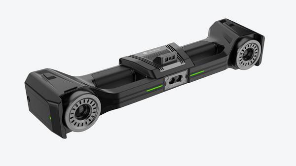
Deployment Validation Checklist
| Focus Area | Decision Point | Deployment Note |
|---|---|---|
| Target part | Check size, surface condition, and key tolerances against the scan task | Run a full trial scan on a representative part |
| Data workflow | Verify point cloud, deviation map, and quality-report handoff | Confirm export formats and review ownership in advance |
| Shop-floor use | Review training, calibration, lighting, and working space | Keep the validation record as a repeatable inspection reference |
The decision most often misjudged is not which scanner has the highest listed point count or the smallest spec-sheet accuracy figure. It is whether the system will work under the actual conditions on your floor, with your existing CAD and inspection software, and with the people who will run it day to day.
A scanner that performs well on a granite table in a demo room can struggle next to a machining cell with vibration, ambient light, and parts that arrive hot, oily, or partially fixtured. Headline accuracy numbers rarely survive contact with those constraints.
That gap between catalog performance and production-floor reality is where implementation risk hides. Teams buy on resolution and frame rate, then discover the alignment workflow fights their CAD package, the software export does not match how the quality lab documents nonconformances, or the operator needs more training time than the project schedule allows. The scanner itself may be capable, but the fit is wrong.
INSVISION industrial 3D scanners are relevant to this conversation because the evaluation should start from the scan object, the inspection task, and the required data deliverable, not from a specification sheet. The guide that follows provides a vendor-neutral validation framework. No rankings, no paid endorsements, no brand-by-brand scoring tables.
Instead, you will find criteria tied to real production constraints: surface finish and part size, environmental conditions, software compatibility, operator skill level, and the downstream use of the scan data. The goal is to help you build a verification checklist that reduces implementation risk and ensures the system you select delivers operational value beyond the purchase order.
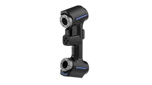
Key Production Floor Pain Points That Drive 3D Scanner Adoption
Most teams don’t replace a CMM or a set of calipers because the instruments lack accuracy. They replace them because the measurement workflow no longer matches the part geometry, the production cadence, or the documentation burden.
On a Western production floor operating under lean manufacturing rules or ISO/ASME quality systems, that mismatch shows up as queue time, disputed data, and inspection records that look complete but don’t actually close the loop.
The following four pain points are the ones that most often trigger a serious evaluation of an industrial 3D scanner like the INSVISION category of systems, not because scanning is newer, but because it removes a specific bottleneck.
First, contact measurement bottlenecks on complex geometric parts. A prismatic bracket with a few flat datums is fast to check with calipers or a CMM. The problem starts when first-article inspection involves freeform surfaces, deep pockets, thin-wall sections, or dozens of GD&T callouts spread across a casting or machined forging.
Probing those features point by point can take hours, and while the CMM is tied up, production waits. Takt time suffers, not because machining is slow, but because measurement has become the constraint. A scanner captures the full surface in one session, and the inspector can pull the required GD&T callouts from the mesh afterward. First-article inspection stops being the gate that halts the line.
Second, manual inspection variability. Two inspectors can measure the same bore with the same caliper and record slightly different values because of grip pressure, alignment, or simply where the jaw seats. In an ISO 9001 or AS9100 environment, that variability is not a minor nuisance.
It becomes a non-conformance risk, drives rework, and creates scrap that gets attributed to manufacturing when the real issue is measurement repeatability. When the data collection method is automated through scanning, the repeatability question shifts from operator technique to system setup and part fixturing, which are easier to control and audit.
Third, slow reverse engineering of legacy parts in aerospace and energy MRO. Equipment that was designed decades ago often has no reliable CAD model. When a pump housing, turbine blade fixture, or landing gear component fails, the replacement path depends on capturing the as-built geometry quickly. Traditional manual measurement or even CMM digitizing can take days, during which the asset sits idle.
An industrial 3D scanner can capture the full part in a fraction of that time, producing a mesh that goes into CAD for repair or remanufacture. The downtime reduction is often the primary justification.
Fourth, in-process inspection gaps. If a defect enters at station three and is not caught until final assembly, the cost multiplies. But adding full CMM checks at every station is rarely practical. Portable scanning changes that calculus because it can be deployed at the line, capturing critical features before the part moves downstream. That early catch reduces the chance of warranty claims and recall exposure later.
One common thread runs through all four scenarios. Teams often describe the problem as insufficient measurement accuracy, but the real issue is tool-to-workflow misalignment. The accuracy was usually fine. The method was too slow, too operator-dependent, too slow to digitize, or too late in the process. That distinction matters because it changes the evaluation criteria.
The question is not whether a scanner can beat a CMM on a calibration artifact. The question is whether it can capture the right geometry fast enough, repeatably enough, and early enough to keep production moving and keep the quality system defensible.
4 Non-Negotiable Validation Criteria For Industrial 3D Scanners
The purchase decision that most often goes wrong is not about accuracy. It is about fit. A scanner can pass every spec sheet test in a lab and still fail on a production floor because the CAD package will not accept its native output without rework, or because operators need two weeks of retraining before the first meaningful measurement happens. Those failures show up after the purchase order closes.
The four validation criteria below are meant to be checked before that point, while the scanner is still a candidate rather than a fixed asset.
Workflow Compatibility
Start with the software chain, not the hardware. Ask the vendor to demonstrate a round trip from the scanner into your existing CAD environment. If your team works in CATIA or SolidWorks, the delivered data should move into those packages without an intermediate conversion step that strips GD&T callouts or breaks feature trees. The same applies to quality management software.
If the scanner exports a point cloud that then requires manual meshing, decimation, and repair before inspection can begin, that labor cost belongs in your evaluation. A realistic test is to take one actual production part, scan it, and measure the time from scan start to a usable report in your QMS.
If that time does not align with production takt time, the scanner will become a bottleneck even when its raw measurement speed is fast.
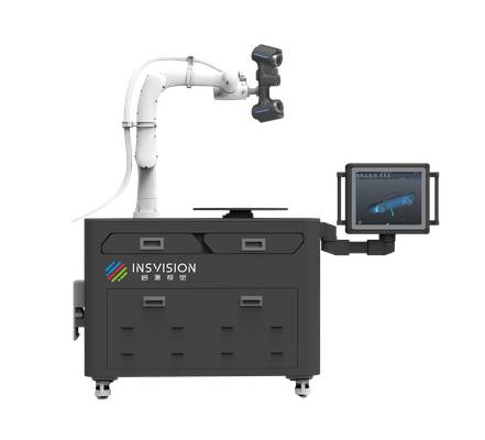
Environmental Resilience
Production floors are not metrology labs. Ambient light shifts when bay doors open. Temperature drifts between morning startup and afternoon operation. Dust from nearby machining settles on optics. A scanner that requires tightly controlled conditions will deliver inconsistent results in that environment, regardless of its stated resolution.
When evaluating an industrial 3D scanner, ask about operating temperature range, humidity tolerance, and ingress protection as a system rather than as isolated values. For example, INSVISION industrial 3D scanner hardware is designed for production environments, but the real question is whether the validation test replicates your conditions. Do not accept a demo in a quiet conference room.
Request a trial on the actual line, during normal operation, with the same ambient light and airborne particulates present.
Data Deliverable Alignment
The file format question seems basic, but it causes more post-purchase friction than any other single issue. Confirm that the scanner supports standard formats such as STEP, IGES, and DWG, and confirm what happens to the data when it arrives in your post-processing tools. Some systems produce a clean surface model.
Others deliver a dense point cloud that requires downstream software investment before it becomes useful for inspection or reverse engineering. The validation step is straightforward: send a sample dataset from the vendor to your engineering team and let them attempt the full workflow without vendor assistance.
If they cannot produce a usable deliverable within a day, the format compatibility claim is not operationally meaningful.
Operational Accessibility
The best scanner is the one your existing quality staff will actually use. If the system requires a dedicated metrology specialist, it will sit idle when that person is unavailable. If the interface assumes deep knowledge of point cloud processing, routine inspection tasks will migrate back to manual methods out of frustration.
Ask the vendor to train two or three of your current quality technicians, then step away and observe what happens. Can they set up a part, capture data, and generate a report without calling support? Training time and repeatability here are more predictive of long-term ROI than any isolated accuracy specification.
Criteria and Validation Summary
The table below organizes the four criteria into a practical verification checklist for evaluators.
Criteria Category | What to Verify | Concrete Validation Step
Workflow Compatibility | Native CAD and QMS integration, takt time alignment | Run one production part through scan-to-report in your actual software chain
Environmental Resilience | Performance under variable temperature, humidity, dust, ambient light | Trial on the production floor during normal operating conditions
Data Deliverable Alignment | STEP, IGES, DWG support; downstream tool compatibility | Engineering team processes a sample dataset without vendor help
Operational Accessibility | Training burden, ease of routine inspection | Train existing quality staff, then observe unassisted use
When these four criteria are validated together, the decision becomes less about marketing claims and more about how the scanner will perform next Tuesday morning on second shift. That is the standard that matters.
How INSVISION Supports Risk-Free Industrial 3D Scanner Validation
The conversation around industrial 3D scanning has shifted. Five years ago, most manufacturers treated scanning as a lab tool. Today, quality leads and manufacturing engineers are pushing these systems directly onto the production floor, integrating them into first-article inspection, MRO reverse engineering, and in-process defect detection.
This move creates a new problem: how do you validate a scanner against your actual parts, tolerances, and shop-floor conditions before committing capital? The wrong assumption here is costly. A scanner that holds accuracy in a controlled demo room can struggle with ambient vibration, oily surfaces, or awkward part geometries on a live line. INSVISION has built its validation approach around this specific risk.
The core issue is rarely the scanner’s published specifications. It is the gap between lab performance and production reality. A quality manager evaluating an escaner 3D industrial for first-article inspection needs to know whether the system can capture a deep pocket, a sharp edge, or a reflective machined surface under the same lighting and temperature swings the operator faces daily.
Published accuracy figures do not answer that. INSVISION application engineering teams start with use-case mapping. They sit down with customer quality and manufacturing staff, pull actual CAD files and sample parts, and define exactly what the scanner must resolve: a 0.1 mm profile tolerance on a sealing surface, a runout callout on a turned diameter, a surface profile on a composite layup.
This step forces clarity before any equipment moves on site.
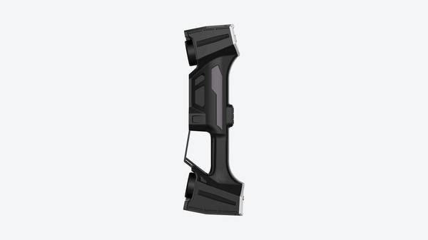
The second phase is where most validation programs fall short. INSVISION conducts proof-of-concept testing in the customer’s own production environment. Not a conference room. Not a clean metrology lab. The scanner is set up next to the machine cell or inspection bench where it will actually live. Parts are scanned with production lighting, production temperature, and production time pressure.
The resulting point clouds and inspection reports become the verifiable proof element, data the customer can compare directly against their CMM results or existing inspection methods. This removes the guesswork from the purchase decision.
The third piece is integration. A scanner is only useful if the operator can run it without a PhD and the output drops into existing workflows. INSVISION provides tailored training and integration support. That means working with the customer’s CAD environment, their inspection software, their report formats. The goal is not to hand over a tool. It is to make sure the tool fits the way this specific plant already works.
For MRO reverse engineering, that might mean a clean STL handoff to CAM. For in-process defect detection, it might mean a simple pass/fail flag on the operator’s screen.
This collaborative approach changes the procurement conversation. Instead of asking which scanner has the best spec sheet, the customer asks which scanner can be proven to work on their parts, in their plant, with their people. That is the risk-free path.
INSVISION method eliminates the most common failure mode in industrial 3D scanning adoption: a system that performs beautifully in a controlled demo and then disappoints on the production floor. For Western manufacturers operating under ISO or ASME quality systems, this validation-first approach aligns with how they already evaluate other capital equipment.
It treats scanning as an engineering decision, not a technology purchase. The result is a solution that actually delivers value where the work happens.
Practical FAQ For Escaner 3D Industrial Evaluation
Most teams misjudge one thing early in scanner evaluation: they compare specs before they compare workflows. The right question is not “can it scan faster” but “can it drop into our inspection sequence without creating new bottlenecks.” These four FAQs address the sticking points that usually surface after procurement, not before.
Can an industrial 3D scanner replace a CMM for first-article inspection?
Sometimes, but not universally. If tolerances are tight on GD&T callouts like true position or profile, a scanner may not match CMM repeatability on every feature. Suitability depends on part geometry, required tolerance band, and inspection volume. For prismatic parts with a handful of critical dimensions, a CMM often remains the better tool.
For complex freeform surfaces or high-density point cloud comparison to CAD, scanning adds clear value. Before committing, run side-by-side tests against your existing CMM on the same parts. Align both datasets to ASME GD&T standards and check measurement variation across multiple operators and shifts.
If the scanner consistently falls inside your accepted CMM uncertainty band for non-critical features, you can shift some workload over. If not, keep both tools in the loop.
What file formats should a production-ready industrial 3D scanner support?
Look for native export of STEP, IGES, STL, and DWG at minimum. STEP and IGES matter for CAD comparison and reverse engineering. STL is standard for mesh-based inspection software. DWG support helps when scan data feeds layout or documentation workflows. Beyond the format list, ask about post-processing time. Some systems export raw point clouds that require heavy cleanup before your quality software can use them.
That hidden labor cost erodes the productivity gain. A production-ready scanner should deliver files your team can open, align, and analyze without a dedicated data-processing specialist. During evaluation, request a sample dataset from a part similar to yours and test the full import-to-report sequence inside your existing CAD and quality management tools. If formatting or alignment takes hours, treat that as a workflow risk.
Do industrial 3D scanners require a temperature-controlled lab environment?
Not necessarily. Industrial-grade models are designed to operate in variable production floor conditions, with many rated for broad temperature and humidity ranges. INSVISION industrial 3D scanner equipment, for example, is engineered around real factory environments rather than clean lab settings. But accuracy can shift under extreme temperature swings, airborne dust, or nearby vibration from stamping presses or CNC spindles.
The only reliable way to know is an on-site trial. Place the scanner at your intended inspection station, scan a reference artifact at morning and afternoon temperatures, and compare the results. If measurements stay within your tolerance band across those conditions, the location works. If not, you may need a simple enclosure or a different mounting position. Do not accept a vendor’s lab spec as proof of floor performance.
How much training does a quality team need to use an industrial 3D scanner effectively?
It depends on scanner complexity and the team’s existing metrology experience. An operator familiar with CMM programming or laser scanning will typically pick up basic workflows faster than someone coming from manual gauging. Some systems require deeper software configuration for automated inspection routines; others are more turnkey.
Ask the vendor for a defined training plan: how many days of on-site instruction, what tasks operators can run independently afterward, and what ongoing support is included. The practical test is whether your existing staff, not the vendor’s application engineer, can complete routine scans and generate inspection reports within a reasonable onboarding window.
If the answer requires weeks of specialized training or dedicated programming support for basic jobs, factor that into total cost of ownership.
Validation checklist for vendor conversations
Confirm workflow integration with existing CAD, CMM, and quality management tools. Request on-site testing in your actual production environment, not a demo lab. Verify file format compatibility using your own parts and software. Review training scope, support response times, and post-installation assistance before signing.
Hangzhou Insvision Technology Co., Ltd.
Address: Building 1, No. 1399 Liangmu Road, Yuhang District, Hangzhou, Zhejiang 311121, China
Copyright © Hangzhou Insvision Technology Co., Ltd. All rights reserved.
Copyright © Hangzhou Insvision Technology Co., Ltd. All rights reserved.