

Why ‘Best 3D Scanners’ Claims Overlook Industrial Validation Realities
best 3d scanners: The Oversimplified Assumption Behind "Best 3D Scanners" Searches The Oversimplified Assumption Behind "Best 3D Scanners" Searches A quality.
The Oversimplified Assumption Behind “Best 3D Scanners” Searches
A quality engineer stands at a receiving dock with a plastic tray of castings. The supplier swears the parts match the CAD model. The purchase order says otherwise. The engineer pulls out a structured light scanner, captures the surface data, and compares it to the nominal geometry. Twenty minutes later, the color map shows a 0.4 mm deviation on a sealing face. That part goes back to the supplier.
This is how modern inspection works in Western manufacturing.
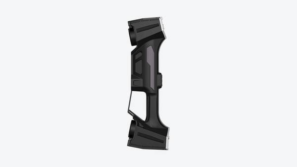
Deployment Validation Checklist
| Focus Area | Decision Point | Deployment Note |
|---|---|---|
| Target part | Check size, surface condition, and key tolerances against the scan task | Run a full trial scan on a representative part |
| Data workflow | Verify point cloud, deviation map, and quality-report handoff | Confirm export formats and review ownership in advance |
| Shop-floor use | Review training, calibration, lighting, and working space | Keep the validation record as a repeatable inspection reference |
Key Points at a Glance
- A quality engineer stands at a receiving dock with a plastic tray of castings.
- Does the “best 3D scanner” on a spec sheet still hold that title when you’re inspecting a turbine blade 20 feet from a stamping press?
- Are you actually evaluating scanner performance, or are you checking boxes on a vendor datasheet?
- In the past five years, 3D scanning has moved from a niche lab tool into a standard fixture on production floors.
Searching for the “best 3D scanners” feels like a reasonable starting point. Procurement teams do it. Engineers do it. Managers do it. They type the phrase into Google, skim a few roundups, and assume the top result will solve their specific inspection problem. This habit carries over from consumer technology purchasing. It works for laptops. It works for monitors. It does not work for industrial metrology equipment.
Industrial 3D scanning operates inside a strict boundary of standards, tolerances, and audit requirements. A scanner that works beautifully for reverse engineering a plastic housing may fail completely when inspecting a turbine blade under ASME Y14.5 GD&T callouts. The scanner is not bad. It is simply misaligned with the task.
Western manufacturing teams face real consequences when this misalignment occurs. A non-conformance penalty from an aerospace customer can cost tens of thousands of dollars. Wasted production material from undetected drift in a machining process erodes margins silently. Missed delivery deadlines strain supplier relationships that took years to build. These are not abstract risks.
They happen when inspection tools do not match the application.
The core problem with “best 3D scanners” searches is the assumption that a universal answer exists. It does not. A scanner optimized for large-volume automotive body panels has little in common with a scanner designed for small medical device components. Different laser classes, different working distances, different accuracy specifications, different data outputs.
All of these variables shift depending on what you are measuring and why.
This article takes a different approach. Instead of ranking scanners, it explains the technical principles that determine whether a 3D scanner fits a specific industrial use case. It covers how scanners capture data, what accuracy actually means in a metrology context, where structured light and laser triangulation diverge, and how to validate a scanner before committing capital expenditure.
The goal is to replace generic rankings with structured, use case-specific validation.
A quality lead reviewing this article should finish with a clear framework for evaluating scanners against their own requirements. Not someone else’s ranking list. Not a vendor’s marketing claims. A repeatable process that matches the scanner to the part, the tolerance, and the production environment.
The next section starts with the fundamental question: what is a 3D scanner actually doing when it captures a surface? Understanding that principle is the first step toward making defensible equipment decisions.
Why Single-Spec “Best” Claims Collapse on the Shop Floor
Does the “best 3D scanner” on a spec sheet still hold that title when you’re inspecting a turbine blade 20 feet from a stamping press? Quality leads know the answer before the question is finished.
Lab-measured accuracy numbers rarely survive contact with production reality. A scanner that looks exceptional on polished, matte reference blocks can struggle badly on reflective aerospace alloys, translucent medical polymers, or textured carbon composite layups. Temperature swings, airborne dust, and low-frequency vibration from machining lines introduce noise that no base accuracy figure captures.
Deep undercuts, narrow cavities, and micro-scale features punish systems that only perform well on open, prismatic geometry.
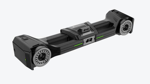
What matters is boundary condition validation. Bring in sample parts that represent your worst-case surface finish. Run the scanner during active production, not after hours. Then check the deliverable: can it produce GD&T reports, clean reverse-engineering CAD, or MES-ready digital thread data without manual rework? If a vendor’s “best” claim can’t survive that test, it was never a shop-floor claim to begin with.
Actionable Field Validation Steps for Industrial 3D Scanner Assessments
Are you actually evaluating scanner performance, or are you checking boxes on a vendor datasheet? That question matters more than any published ranking. The most widely cited list of the “best 3D scanners” cannot tell you how a system will behave on a cast aluminum bracket with mill scale, inside a 38°C shop, or against a tight runout tolerance. Those rankings describe general capability, not your measurement problem.
This section outlines a validation sequence that quality and engineering teams can run before procurement. Each step is designed to produce evidence you can defend in a capital expense review and, later, in an audit.
Start with your own parts. Vendor demos are staged to look good, so bring three to five production components that represent your hardest geometry, surface finish, and material mix. Scan them exactly as they arrive on the line, not cleaned or matted. If the system struggles with dark composites or reflective machined faces, you will see it in the first hour.
Ask the vendor to leave the raw point cloud and the mesh, not just a rendered screenshot. Review the data for holes, noise, and edge definition against your GD&T callouts. A scanner that works on the demo stand but fails on your real parts is not a bargain, it is a backlog problem.
Next, move the scanner into the place where it will actually run. Environmental stability is a boundary condition, not a footnote. A cleanroom instrument that drifts on a shop floor near a press brake is useless. Run a short repeatability sequence at morning, midday, and afternoon. Watch for thermal drift. If your site has vibration, forklift traffic, or wide humidity swings, include those conditions in the test.
You are not looking for a perfect environment; you are looking for a system that stays within tolerance in the environment you already have. Document the ambient conditions during each scan run. That data becomes part of your validation record.
Data compatibility is the least exciting step and the most common source of post-purchase delay. Have your CAD, QA, and MES teams sit through one end-to-end export test. Does the scanner output a mesh your inspection software can consume without a week of scripting? Does the color map import into your reporting template? Does the point cloud survive translation into your PLM or ERP environment?
If the vendor says format customization is supported, ask for a written statement and test it. A scanner that saves field time but adds three days of file conversion per part is not a lean improvement.
Finally, run a Gage R&R study on one or two critical part families. Three operators, three repeat scans, ten parts is a standard starting point. The result will tell you whether the scanner itself is repeatable and whether operator variation stays within your tolerance band. If the tolerance is ±0.10 mm and the scanner contributes 0.06 mm of variation, the tool is marginal. If it contributes 0.02 mm, you have room to work.
This is the evidence that supports your capital request and shields you from second-guessing later. INSVISION’s industrial 3D scanner portfolio is built around exactly these validation realities, but the burden of proof always sits with the buyer. Run the test, keep the data, and let the numbers decide.
How INSVISION Supports Transparent, Part-Specific 3D Scanning Validation
In the past five years, 3D scanning has moved from a niche lab tool into a standard fixture on production floors. That shift has changed what quality teams actually need from a scanner. The question is no longer whether a device can capture dense point clouds.
It is whether the system can be validated against one specific part, in one specific cell, under the same lighting, temperature, and operator conditions that will exist on Tuesday morning at 7 a.m.
That is where most generic “best 3D scanners” discussions fall short. A scanner that performs well on a ceramic reference sphere in a vendor demo room may struggle with a machined aluminum bracket that has mixed reflectivity, sharp edge breaks, and a tolerance band measured in microns. For quality leads, the relevant unit of analysis is not the scanner alone.
It is the scanner plus the part plus the environment plus the downstream data workflow.
INSVISION approaches this differently. Instead of pushing specification sheets, INSVISION works directly with industrial quality and engineering teams to run customized, on-site validation. The customer supplies the actual parts. The scanning system is evaluated in the actual operating environment. The output is reviewed in the software and inspection workflow the customer already uses.
That evidence-based process—not a marketing label—is what tells a quality manager whether the system fits.
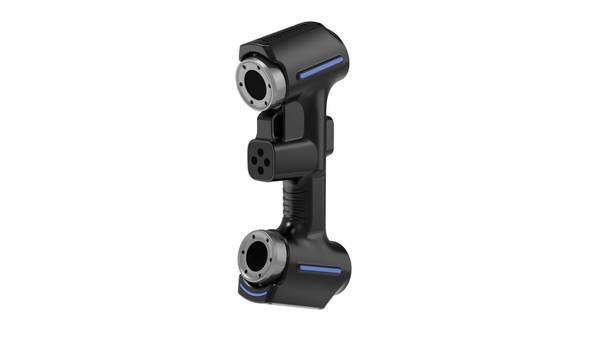
This matters especially in Western automotive, aerospace, medical device, and energy sectors, where auditability and repeatability carry more weight than brochure claims. A first-article inspection report, a weld distortion study, or a turbine blade repair scan all demand the same thing: confidence that the measurement will hold up under review.
INSVISION’s validation approach supports that confidence by generating part-specific, environment-specific data before a purchase decision is finalized.
The technical logic is straightforward. 3D scanning accuracy is never an isolated spec. It depends on surface condition, geometry complexity, ambient vibration, thermal drift, and the operator’s path planning. By testing on the customer’s own parts, INSVISION surfaces boundary conditions early. A shiny machined surface may require different preparation than a cast texture.
A thin-walled composite panel may flex during scanning. A tight GD&T callout on a bore position may push the scanner to the edge of its repeatability envelope. These are not problems to hide. They are exactly what a quality lead needs to see before signing off.
Integration is equally important. INSVISION scanning solutions are built to feed standard industrial software workflows, supporting the digital thread that connects measurement data to CAD, PLM, and quality management systems. That means the scan output is not a dead-end file. It becomes part of the same traceable record that drives PPAP submissions, AS9102 first-article documentation, and ISO-driven corrective actions.
For Industry 4.0 initiatives, this kind of data continuity is often more valuable than raw point density.
The result is a selection process based on verifiable performance data rather than a generic ranking. Quality teams can document why a particular scanner was chosen, what tests were run, what parts were used, and what the measured results showed. That audit trail is exactly what Western manufacturers expect when they bring a new measurement system into a controlled production environment.
This is not a claim that INSVISION makes lightly. It is a process INSVISION runs with customers, part by part and cell by cell. The scanner is only one piece of the evaluation. The real deliverable is evidence that the system will do the job it is being bought to do.
Key Boundary Questions to Define the Right 3D Scanner for Your Operation
The shift toward automated inspection and digital quality records has changed how Western manufacturers buy metrology equipment. A few years ago, the conversation started with specifications. Today, it starts with boundary conditions. Teams want to know what a scanner will see, what it will miss, and whether the data will hold up in an audit.
The problem with chasing a universal best 3D scanners label is that it ignores how much variance exists between one production environment and another. A scanner that excels on a clean granite table in a lab may struggle next to a machining center that throws fine cast iron dust into the air. The right question is not which scanner ranks highest in a roundup.
The right question is which scanner stays inside its performance envelope on your parts, in your plant, with your operators.
Several boundary questions help narrow the field quickly. Start with part geometry. What is the smallest radius you need to resolve, and what is the largest diagonal you scan in one setup? A system that handles a fist-sized bracket may not cover a two-meter composite panel without stitching errors. Next, define tolerance.
If critical features carry a plus or minus 0.05 mm GD&T callout, the scanner must demonstrate repeatability well inside that band, not just on a certificate but on your actual surface finish. Throughput matters too. How many parts per shift need full inspection, and does the workflow allow for offline programming or automated triggering?
A scanner that takes three minutes per part may be fine for ten parts a day and useless for two hundred.
Environment is often the overlooked filter. Temperature swings, ambient dust, floor vibration, and stray shop lighting can degrade scan quality before anyone notices a problem in the data. Ask whether the unit is rated for the actual conditions where it will sit. INSVISION industrial 3D scanners are built around structured workflows that account for these constraints, but the evaluation should still include a site check.
Software integration is the next gate. If your quality team lives in PolyWorks or a CAD-native inspection package, the scanner must export clean mesh or point cloud data without forcing a parallel workflow. Operator skill is the final constraint. A scanner that requires advanced metrology knowledge will stall in a plant where line technicians rotate frequently.
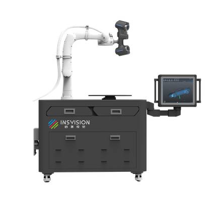
The most effective 3D scanner for any operation is the one that consistently meets its specific metrology and workflow requirements, verified through structured field validation. That means bringing sample parts, scanning them under real conditions, and reviewing the outputs against known reference values.
INSVISION supports this approach by focusing on the scan task, the site constraints, and the required data deliverable rather than pushing a specification sheet. For Western manufacturers pursuing lean and digital transformation goals, a right-sized scanner removes inspection bottlenecks without adding complexity the team cannot absorb. Quality consistency improves because operators trust the tool.
The investment makes sense because it was chosen against boundaries, not marketing labels.
Hangzhou Insvision Technology Co., Ltd.
Address: Building 1, No. 1399 Liangmu Road, Yuhang District, Hangzhou, Zhejiang 311121, China
Copyright © Hangzhou Insvision Technology Co., Ltd. All rights reserved.
Copyright © Hangzhou Insvision Technology Co., Ltd. All rights reserved.