

Affordable Hand Held 3D Scanners Power End-to-End Quality Inspection Workflows
In many Western manufacturing plants, the gap between quality inspection and production throughput has become one of the quietest drains on operating margin.
Common Shop-Floor Quality Inspection Bottlenecks Impacting Production Throughput
Are you losing production hours to measurement bottlenecks that nobody tracks as a formal cost line? In many Western manufacturing plants, the gap between quality inspection and production throughput has become one of the quietest drains on operating margin. Automotive Tier 1 suppliers face lean efficiency targets that leave little room for inspection wait states.
Aerospace MRO facilities carry ISO and ASME compliance burdens that make every non-conformance expensive. Medical device contract manufacturers, meanwhile, are caught between tightening traceability requirements and a shrinking pool of skilled metrology labor.
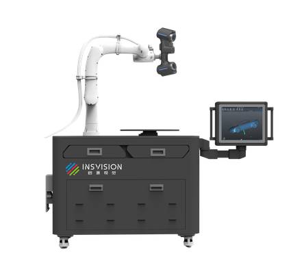
Deployment Validation Checklist
| Focus Area | Decision Point | Deployment Note |
|---|---|---|
| Target part | Check size, surface condition, and key tolerances against the scan task | Run a full trial scan on a representative part |
| Data workflow | Verify point cloud, deviation map, and quality-report handoff | Confirm export formats and review ownership in advance |
| Shop-floor use | Review training, calibration, lighting, and working space | Keep the validation record as a repeatable inspection reference |
Key Points at a Glance
- Are you losing production hours to measurement bottlenecks that nobody tracks as a formal cost line?
- In most shops, the handoff between quality engineering and production still carries too much overhead before a single measurement is taken.
- The shift toward in-cell metrology has changed how quality teams think about inspection routing.
- The real payoff from affordable hand held 3D scanners shows up after the scan, when the raw point cloud moves from the shop floor to the quality…
The friction often sits inside traditional inspection workflows. Manual calipers are slow and operator-dependent. Fixed CMMs create queues. Stationary 3D scanners, while useful, lock inspection to one location. The result is a familiar pattern: setup wait times grow, non-conformance alerts arrive late, manual data entry introduces errors, and rework loops stretch delivery timelines.
Affordable hand held 3D scanners are changing that equation. They allow quality and production teams to share inspection data at the point of work, rather than routing parts through a centralized lab. This article looks at the end-to-end workflow — from first-article checks to in-process verification — for readers evaluating cost-efficient quality tools that fit real shop-floor constraints.
Streamlined Pre-Scan Preparation for Cross-Team Shop-Floor Deployment
In most shops, the handoff between quality engineering and production still carries too much overhead before a single measurement is taken. A quality engineer prepares the inspection plan, verifies the master CAD revision, confirms GD&T callouts, and then coordinates with the cell operator for part staging.
The operator, in turn, must align the part on a fixture, call up the correct program, and wait for a fixed CMM or gauge system to run through its cycle. That sequence works when everything lines up. It falls apart quickly when the work order changes mid-shift, when a fixture is missing, or when the part is too large or awkward to move to the metrology lab.
Affordable hand held 3D scanners change the prep burden because they move the measurement task to the part, not the part to the measurement system. For a quality engineer, that means less time spent defining fixture setups and more time validating that the correct master CAD file is synced with the production work order.
For a production operator, it means positioning a part on a bench or in a cell, scanning it in place, and letting the software handle alignment. The scanner’s mobility supports low-fixture or no-fixture setups, which removes one of the most common prep bottlenecks in first-article inspection and in-process checks.
From a process control view, the preparation step should not require advanced metrology training. Baseline GD&T configuration per ISO 10360 or ASME Y14.5 can be set up by quality engineering ahead of time, then applied consistently by line operators. The operator does not need to interpret datums or tolerance zones on the fly. They follow the work order, position the part, and capture data. Exceptions get flagged for review.
That separation of responsibility keeps production moving while maintaining quality traceability.
INSVISION hand held 3D scanners are designed for this kind of shop-floor deployment. The intent is to reduce the friction between quality teams and line operators, not to add another specialized tool that only a CMM programmer can run.
When the scanner is intuitive enough for production staff to support basic inspection tasks, the quality engineer spends less time on routine prep and more time on exception review and process improvement. That is the operational value: shorter setup time, fewer fixture dependencies, and a smoother handoff between engineering and production.
On-Floor Scan Path Execution for Real-Time Cross-Team Quality Visibility
The shift toward in-cell metrology has changed how quality teams think about inspection routing. Instead of staging parts through a dedicated lab, manufacturers now run scan paths directly at the production cell.
This matters for parts that carry tight GD&T callouts across freeform surfaces: automotive cast brackets with draft and fillet transitions, turbine blade airfoils with leading-edge curvature, and medical implant components where surface continuity affects downstream finishing.
INSVISION handheld 3D scanners fit this workflow because the operator can walk the scan path around the part without breaking setup. For a cast bracket, that means starting on the datum face, sweeping across the machined pads, then rolling the scanner to capture the as-cast flanges. For an airfoil, the path follows the chord line first, then the radius blend at the platform.
Implant trays and stems require slower, overlapping passes across polished surfaces.
The practical benefit is coverage confidence before the operator leaves the station. Real-time preview shows data density on screen. Thin or missing patches get flagged immediately. The operator can re-sweep a local area instead of the quality engineer discovering the gap hours later and requesting a full re-scan. That single loop closes a common source of rework.
Handheld mobility also removes transport time. Parts stay at the cell. Work-in-progress inventory does not sit in a queue outside the metrology lab. For aerospace MRO or medical device lines, this shortens the time between machining, inspection, and disposition. Quality engineers can review the captured mesh on-station or remotely, compare against nominal CAD, and approve or reject without walking the part back and forth.
Miscommunication drops because both teams see the same scan data at the same time.
For complex geometries, scan path best practices still apply. Keep the scanner normal to the surface where possible. Overlap passes by roughly one-third of the field width. On shiny or dark surfaces, apply a thin developer spray before scanning. When unexpected features appear, such as a weld repair or a hand-blended radius, the operator can adjust the path on site. No need to wait for a revised inspection plan.
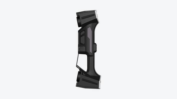
INSVISION scanners support this with lightweight, ergonomic handling and scan preview that updates as the operator moves. The result is a quality record that reflects the actual part condition at the time of manufacture, not a delayed snapshot after the part has already moved to the next operation.
Point-Cloud Processing and Deviation Analysis for Standardized Exception Reviews
The real payoff from affordable hand held 3D scanners shows up after the scan, when the raw point cloud moves from the shop floor to the quality engineering team. That handoff is where most inspection workflows either tighten up or fall apart. The scanner operator captures the data, but the value gets created in how cleanly that data can be processed, aligned, and reviewed against the design intent.
INSVISION scanners are built with that downstream workflow in mind, not just the capture step.
The first processing stage is automated point-cloud cleanup. Handheld scanning produces noise, stray points, and artifacts from reflections or edge effects. Quality engineers need software that can strip those out without eating hours of manual editing time.
A good cleanup routine preserves the actual surface data while removing outliers, so the scan becomes a reliable representation of the physical part rather than a messy raw dataset. This matters because every downstream step depends on that foundation.
Next comes alignment to the master CAD model. The scan data has to be registered to the nominal geometry before any deviation analysis makes sense. Modern processing platforms handle this through best-fit algorithms, datum-based alignment, or feature-based registration. The goal is to get the scanned point cloud sitting exactly where the CAD model sits in virtual space.
If alignment is off, every subsequent deviation value is meaningless. Quality teams typically run this as a semi-automated step with manual verification of datum features.
Once aligned, the GD&T deviation analysis begins. This is where the scan data gets compared against dimensional callouts, profile tolerances, and position requirements. The output is typically a color map showing where the part deviates from nominal, with green zones in tolerance and red zones out of spec. Engineers can click on any point to pull the actual deviation value and compare it against the tolerance band.
That visual output is what makes the exception review process so much faster than traditional methods.
The shift away from handwritten measurement logs and 2D reports is significant for cross-functional collaboration. When a non-conformance shows up, the quality engineer and the production engineer can sit down together and look at the same 3D color map. There is no ambiguity about which feature was measured, how the measurement was taken, or what the numbers actually mean.
The part geometry is right there on screen, with the deviation clearly visualized. That shared visual dataset cuts root cause analysis time because the conversation starts from the same factual picture instead of conflicting interpretations of a handwritten log.
This also changes how exception reviews get documented. Instead of a paper trail of measurement sheets, the scan data itself becomes the record. The point cloud, the alignment, the deviation map, and the GD&T callouts all live in one digital file. Quality management systems can store that file with the part serial number, the date, the operator, and the machine settings.
Traceability stops being a manual filing exercise and becomes a natural byproduct of the scanning workflow. When a customer or auditor asks for dimensional evidence on a specific part, the team can pull up the full 3D dataset rather than a scanned PDF of a handwritten form.
INSVISION handheld scanners output data in formats that plug into widely used quality and engineering software platforms. That compatibility matters for integration with existing QMS infrastructure. Companies do not need to rip out their current quality software or retrain the entire engineering team on a proprietary ecosystem.
The scan data flows into the tools they already use for GD&T analysis, statistical process control, and non-conformance tracking. That reduces the implementation friction and makes the scanners a practical addition to the existing quality stack rather than a disruptive technology change.
Inspection Report Delivery and Closed-Loop Quality Process Integration
The shift toward closed-loop quality systems has changed what manufacturers expect from inspection. A measurement is no longer the final deliverable. The report is. And for Western job shops and OEMs running lean production lines, that report needs to move as fast as the part itself.
Affordable hand held 3D scanners have pushed this capability down to smaller plants that previously relied on manual gauging and paper check sheets. With INSVISION equipment, the scan-to-report workflow closes the loop between the shop floor and the quality office without adding headcount.
The final deliverables from a 3D scanning workflow fall into three operational buckets. First, standardized internal inspection reports. Color-mapped deviation plots, GD&T callout pass/fail status, and dimensional tables all drop into a repeatable PDF or CSV format. Quality engineers stop rebuilding report templates for every job. Second, customer-facing compliance documentation.
Aerospace and medical device buyers increasingly request digital dimensional data with the shipment, not just a signed CofC. A scan report attached to the order package answers that requirement without a separate layout inspection. Third, structured process adjustment recommendations. When the same feature drifts across three consecutive lots, the scan data shows it before a CMM programmer or a machinist notices.
Production teams get a corrective action target, not just a rejection notice.
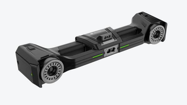
The operational value sits in the time between part production and quality sign-off. Traditional layout inspection on a surface plate can take hours for a complex casting or weldment. A hand held scanner captures the same geometry in minutes, and the software generates the report on the spot. For high-priority jobs, that compresses the release cycle.
A first-article inspection that used to wait for a CMM opening can be completed at the machine. Shipping doesn’t stall. Order cadence tightens.
Long-term, the value shifts from speed to traceability. Structured digital quality records per part serial number create a searchable history. When a lean kaizen team reviews scrap trends, they aren’t digging through file cabinets. They query the scan database. Industry 4.0 analytics work the same way.
Recurring process drift on a bore diameter or a flange flatness shows up as a pattern across parts, not as an isolated bad day. The team corrects the process before scrap or rework accumulates. That’s the real cost efficiency: not catching bad parts faster, but preventing them from happening in the first place.
Reinspection Workflows and Recurring Quality Validation for Consistent Output
Most shops still treat reinspection as a necessary evil, not a lever for consistency. The assumption is that rechecking a reworked part or a new first-article run takes too long, ties up skilled inspectors, and delays the line. That assumption breaks down once you put an affordable hand held 3D scanner at the production station instead of routing everything through the metrology lab.
Non-conforming part rework verification is the most immediate win. After a machinist adjusts an offset or re-cuts a feature, the scanner captures the updated surface geometry on the spot. The operator sees whether the correction brought the feature back within tolerance before the part moves to the next operation. No waiting for a CMM queue. No second setup on a surface plate.
The scanner becomes a station-level verification tool, not a lab instrument.
Production process adjustment checks follow the same logic. When a process engineer changes a feed rate, tool path, or clamping sequence, the first parts off the line need rapid dimensional feedback. A hand held scanner running a saved scan path gives that feedback in minutes. The engineer can compare the new scan against the stored reference mesh and decide whether the adjustment worked or needs another iteration.
This shortens the loop between process change and validated output.
First-article inspection for new part runs benefits from the same approach, especially in contract manufacturing where new part numbers arrive frequently. Instead of programming a CMM from scratch for every FAI, the quality team builds a scan template once. Production runs the scan, and the software flags deviations from the CAD model or the approved reference scan.
The FAI report populates from the template, so the inspector reviews exceptions rather than manually documenting every dimension.
Periodic tooling wear assessments are where recurring validation pays off most over time. Progressive die wear, mold surface degradation, and fixture drift all show up as small dimensional shifts long before they produce scrap. A saved scan path lets a production operator check critical tooling surfaces on a weekly or monthly cadence.
The scan data accumulates, so the quality team can spot wear trends before they cause a non-conformance. That shifts tooling maintenance from reactive replacement to planned intervention.
The standardization piece matters more than most shops expect. Saved scan paths and report templates remove inspector-to-inspector variability. Two operators on different shifts scan the same part the same way, and the software generates the same report format. New team members learn one scan routine instead of memorizing a dozen manual measurement setups.
Training time drops, and the data becomes comparable across shifts because everyone follows the same capture sequence.
Cross-team alignment improves when quality teams control the inspection criteria centrally and production teams run the physical scans locally. A quality engineer updates the tolerance band or the reference mesh in the software. The production operator on the floor sees the updated requirement on the next scan. No need to reissue paper inspection sheets or retrain operators on a new check.
The scanner becomes the delivery mechanism for the quality standard.
INSVISION hand held 3D scanners fit this workflow because they operate at the production station without a dedicated metrology environment. The scan data exports into standard formats that quality teams can review in their existing inspection software. Production gets the speed of a local check, and quality retains control over the acceptance criteria and data archive.
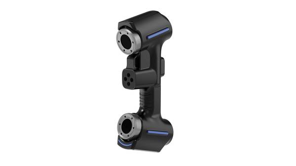
For teams new to hand held 3D scanning, start with one recurring inspection task that currently creates a bottleneck. Rework verification is usually the easiest first use case because it happens frequently and the value is immediately visible. Once that workflow is stable, extend the same saved scan path approach to first-article inspections on repeat part numbers.
Tooling wear assessment can come later, after the team has built confidence in the scan data and the report templates. This staged approach validates the operational value before committing to full deployment across every line.
Hangzhou Insvision Technology Co., Ltd.
Address: Building 1, No. 1399 Liangmu Road, Yuhang District, Hangzhou, Zhejiang 311121, China
Copyright © Hangzhou Insvision Technology Co., Ltd. All rights reserved.
Copyright © Hangzhou Insvision Technology Co., Ltd. All rights reserved.