

3D Scanning Device Core Principles Key Parameters and Industrial Use Cases
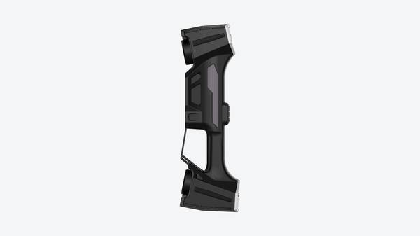
3d scanning device: What Is a 3D Scanning Device? What Is a 3D Scanning Device? A 3D scanning device is a non-contact metrology instrument that captures the.
What Is a 3D Scanning Device?
What Is a 3D Scanning Device?
A 3D scanning device is a non-contact metrology instrument that captures the complete surface geometry of a physical object and converts it into a dense digital point cloud or mesh. Unlike a touch probe that records one discrete point at a time, a 3D scanner projects structured light or laser lines across a surface and measures the distortion of that pattern to calculate millions of coordinates in seconds.
The output is a dimensional 3D model that can be compared against nominal CAD data, used for reverse engineering, or archived as a digital twin.
Term Notes
A 3D scanning device is a non-contact metrology instrument that captures the complete surface geometry of a physical object…
How Do 3D Scanning Devices Operate?A 3D scanning device captures physical geometry without touching the part.
Common Industrial Technology ApproachesStructured light systems project a known pattern — often parallel blue laser lines — onto the surface.
Point Cloud Generation and Model ReconstructionRaw scanner output is not a CAD model.
This distinction matters for industrial applications. Contact measurement remains the reference method for simple, well-defined features such as a bore diameter or a flatness callout. But when a quality team needs to characterize a freeform turbine blade airfoil, map the warpage of an injection-molded housing, or verify the full profile of a stamped automotive bracket, point-by-point probing becomes impractical.
A 3D scanning device fills that gap, providing full-field data at a density that would take a CMM operator days to replicate.
Within Industry 4.0 and lean manufacturing frameworks, the value of 3D scanning extends beyond the inspection lab. The digital models generated by these devices feed directly into closed-loop quality systems, enabling faster first-article inspection, automated root-cause analysis, and reduced scrap. For aerospace MRO operations, a scanner can document as-found wear on a landing gear component before repair begins.
For medical device manufacturers, it supports the validation of complex, organic-shaped implants that do not lend themselves to traditional gaging. In the energy sector, it provides a fast method for assessing corrosion or deformation on large castings and forgings.
It is best to view 3D scanning not as a replacement for contact metrology, but as a complementary tool suited to specific inspection challenges. The selection criteria for a given application are summarized below.
| Application Requirement | Contact Metrology (CMM) | 3D Scanning Device |
|---|---|---|
| High accuracy on simple geometric features | Primary method | Secondary verification |
| Full-surface characterization of complex profiles | Impractical or slow | Primary method |
| High-throughput inspection of multiple features | Slow; point-by-point | Fast; full field in one pass |
| Reverse engineering of legacy parts with no CAD | Limited; sparse data | Primary method |
| Flexible or soft materials | Risk of surface deflection | Non-contact; no deflection |
Modern 3D scanning devices vary in configuration. Some, such as those offered by INSVISION, use blue laser lines in multiple scanning modes—ranging from a single line for deep-hole access to parallel line arrays for high-speed surface capture—with scanning areas up to 650 mm × 550 mm for handheld systems. These specifications are not marketing abstractions;
they define the practical envelope of what a given device can measure in a single acquisition. A quality engineer evaluating a scanner for a specific part family should focus on these parameters rather than on generalized accuracy claims. The right device is the one that covers the required scanning area without stitching errors and delivers sufficient point density for the tightest GD&T callout on the drawing.
How Do 3D Scanning Devices Operate?
How Do 3D Scanning Devices Operate?
A 3D scanning device captures physical geometry without touching the part. The core principle is straightforward: project energy at a surface, record the return signal, and convert that signal into spatial coordinates. Most industrial systems use either structured light or laser-based triangulation because both methods deliver the repeatability and resolution required for dimensional inspection and reverse engineering.
The workflow breaks down into three stages. First, the scanner acquires non-contact measurements across the visible surface. Second, acquisition software converts those measurements into a point cloud — a dense set of XYZ coordinates that represents the part’s external shape.
Third, post-processing tools transform the point cloud into a usable deliverable: a polygonal mesh, a CAD comparison report, or a feature-based model for downstream manufacturing.
Common Industrial Technology Approaches
| Approach | Typical Use Case | Key Consideration |
|---|---|---|
| Structured light (blue LED/laser) | Precision inspection, medium-sized parts | Fast area capture; sensitive to ambient light and surface finish |
| Laser triangulation (single/multi-line) | Deep holes, edges, complex geometries | Better reach into recesses; slower area coverage than structured light |
| Photogrammetry-assisted scanning | Large-scale parts, reference alignment | Provides global accuracy frame; requires coded targets or markers |
Structured light systems project a known pattern — often parallel blue laser lines — onto the surface. Cameras observe the pattern deformation and calculate depth at each pixel. This approach suits precision scanning of parts up to roughly 650mm × 550mm per frame, though actual coverage depends on scanner configuration and standoff distance.
Multi-line modes accelerate data capture on open surfaces, while single-line modes improve access into deep holes or around sharp edges.
Laser triangulation uses the same geometric principle but with a narrower beam. A single line can reach areas that broader structured light patterns cannot resolve cleanly, which matters for aerospace MRO work or machined components with blind cavities. The trade-off is speed: one line collects less data per pass than 17 or 50 parallel lines.
Large-format scanning — parts exceeding two meters per side — typically requires either photogrammetry targets or a wide-area scanner configuration. The scanner still captures local geometry, but the global coordinate frame must be established independently to maintain accuracy across the full measurement volume.
Point Cloud Generation and Model Reconstruction
Raw scanner output is not a CAD model. It is a point cloud: millions of individual coordinates with no surface connectivity. Reconstruction software applies filtering, registration, and meshing algorithms to create a continuous surface representation. For inspection workflows, the point cloud or mesh is then compared against nominal CAD geometry using GD&T callouts and tolerance bands.
Traceability matters here. ISO 10360-series acceptance testing and ASME B89.4.19 performance evaluation provide the framework for verifying that a given scanner achieves its stated accuracy under defined conditions. A scanner without documented verification against these standards cannot support first-article inspection or PPAP submissions in regulated manufacturing environments.
INSVISION industrial scanning platforms support multiple acquisition modes within a single device family — single-line deep hole scanning, 7-line precision scanning, and higher-density multi-line configurations for speed-critical applications. The operational principle remains consistent: controlled light projection, calibrated camera triangulation, and software-driven point cloud reconstruction.
Key Performance Parameters for Industrial 3D Scanning Devices
Evaluating a 3D scanning device for industrial use requires separating datasheet marketing from measurable capability. Engineers and quality managers typically assess a limited set of parameters that directly affect throughput, measurement uncertainty, and workflow integration.
The table below defines the core parameters used in technical evaluations, along with their functional purpose and relevance to common manufacturing and inspection tasks.
| Parameter Name | Definition | Industrial Relevance |
|---|---|---|
| Scanning Area | The maximum surface region captured in a single scan pass or measurement frame. | Determines whether a device suits large castings, sheet metal panels, or small machined features. A larger scanning area reduces the number of passes needed for full part coverage, which matters for automotive body-in-white or aerospace skin panel inspection. |
| Precision Scanning Capability | The configuration of laser lines or structured light patterns used when the priority is low measurement uncertainty and fine feature resolution. | Supports GD&T callouts, first-article inspection, and tooling verification where tight tolerances govern acceptance. Precision modes typically trade scan speed for higher point density and better edge definition. |
| High-Speed Scanning Capability | The configuration of laser lines or patterns used when the priority is rapid surface acquisition. | Enables high-throughput inspection of large or complex geometries without excessive cycle time. Relevant for production-line auditing, reverse engineering of large assemblies, and situations where scan time directly affects cell productivity. |
| Deep Hole Scanning Capability | A dedicated mode, often using a single laser line, designed to capture recessed features, bores, and cavities that wide-pattern modes cannot reach. | Critical for machined components with threaded holes, counterbores, or deep pockets. Without this capability, operators may need manual probing or multiple scan angles, increasing setup time and introducing variability. |
| Scan Data Compatibility | The ability of the device output to integrate with downstream software for inspection, CAD comparison, or reverse engineering. | Affects whether scanned point clouds or meshes can be used directly in metrology software, PLM systems, or CAM workflows. Compatibility gaps force file conversion steps that can degrade data quality or slow the digital thread. |
These parameters are not independent. A device with strong high-speed capability may sacrifice fine-feature resolution, while a precision-focused configuration may struggle with deep recesses. Industrial buyers typically evaluate the parameter set against the specific geometry and tolerance requirements of their parts, rather than treating any single specification as a universal indicator of quality.
Primary Application Boundaries of 3D Scanning Devices
The term “boundary” in this context refers not to hardware limitations, but to the operational envelope where a 3D scanning device delivers measurable return on investment.
In industrial practice, these devices are best suited for applications that require dense surface data, geometric verification against nominal CAD, or rapid capture of complex freeform shapes that would be impractical to measure with traditional contact metrology.
The core value proposition centers on data density and speed. A single scan can capture millions of points, enabling full-field deviation analysis rather than sparse point-to-point checks. This capability is best suited for workflows where form, profile, and surface continuity matter as much as discrete dimensions.
Industrial Application Fit
| Application Sector | Primary Scanning Objectives | Operational Goals Served |
|---|---|---|
| Automotive OEM part inspection | Surface deviation mapping, GD&T verification, assembly interface validation | First-article inspection, production part approval workflow acceleration |
| Aerospace MRO | Reverse engineering of legacy components, damage characterization, repair blending assessment | Reduced aircraft-on-ground time, traceable repair documentation |
| Medical device manufacturing | Custom implant geometry capture, anatomical contour verification | Regulatory submission support, patient-specific device quality records |
| Energy sector | Turbine blade profile analysis, structural component wear mapping | Predictive maintenance scheduling, post-service dimensional validation |
Automotive OEM Part Inspection and Assembly Validation
A 3D scanning device is best suited for automotive applications where stamped, cast, or injection-molded components must be verified against CAD with full-field color mapping. The technology replaces time-consuming fixture-based checks for complex curvature, especially on body panels, interior trim, and powertrain castings.
Assembly validation benefits from scanning mating surfaces to identify interference or gap conditions before physical fitment trials. For lean production environments, this translates to shorter inspection loops and fewer dedicated hard gauges.
Aerospace MRO Component Reverse Engineering and Damage Assessment
In maintenance, repair, and overhaul contexts, a 3D scanning device is best suited for capturing the as-is condition of components that lack current CAD documentation or have sustained in-service wear. Legacy turbine blades, structural brackets, and composite panels can be digitized and reconstructed as parametric models.
For damage assessment, scanning provides quantitative depth and area measurements of impact sites, corrosion, or erosion — data that supports engineering disposition decisions and FAA/EASA repair substantiation.
Medical Device Custom Part Measurement
Patient-matched implants and surgical guides require verification of organic, freeform surfaces where conventional CMM probing struggles. A 3D scanning device is best suited for capturing anatomical contours and comparing them to the designed geometry, ensuring that custom devices meet both dimensional tolerance and surface finish expectations.
The resulting point-cloud documentation supports regulatory compliance under ISO 13485 quality systems, where objective measurement records are mandatory.
Energy Sector Turbine and Structural Component Inspection
Steam and gas turbine components accumulate service-related degradation that must be quantified during outage windows. A 3D scanning device is best suited for measuring blade leading-edge erosion, tip clearance features, and casing distortion. Structural components such as flanges, seals, and combustion hardware benefit from rapid full-surface capture that feeds into remaining-life assessments.
The efficiency gain is particularly relevant when outage duration directly affects revenue loss.
Selection Criteria Summary
| Criterion | Technical Consideration |
|---|---|
| Surface type | Matte, machined, cast, or coated surfaces influence scan quality |
| Required resolution | Fine features demand higher point density |
| Part size range | Scanning area must accommodate largest expected component |
| Environment | Shop-floor vibration and lighting affect repeatability |
INSVISION supplies 3D scanning devices within this application framework, with specifications tailored to the capture requirements of each sector.
Common Misconceptions About Industrial 3D Scanning Devices
Industrial metrology teams often delay adopting a 3D scanning device because of assumptions that no longer match how modern systems actually perform. These beliefs tend to circulate in facilities where the last scan evaluation happened a decade ago, or where handheld scanners were first introduced as laboratory curiosities rather than shop-floor tools.
The corrections below address the most frequent objections raised by quality engineers and manufacturing managers.
Misconception 1: Deployment Requires Extensive Facility Modifications
A persistent belief holds that a 3D scanning device demands a dedicated metrology lab, vibration isolation pads, controlled lighting, and recalibrated temperature zones. That framing fits coordinate measuring machines bolted to granite slabs. It does not describe modern structured-light or laser-based scanners built for portable use.
Industrial handheld scanners operate on tripods or in handheld configurations next to the workpiece. Ambient shop lighting does not blind the sensor. Temperature compensation happens in software. The scanner measures the part, not the room. Facilities do not need to pour new foundations or reroute HVAC before a scan campaign begins.
Misconception 2: Deep or Recessed Features Cannot Be Captured
Engineers sometimes assume that a 3D scanning device only captures line-of-sight surfaces and fails inside deep pockets, narrow slots, or fastener bores. The limitation is real for older single-mode systems. It is not a universal constraint.
Modern industrial scanners include dedicated deep-hole scanning modes. These modes project a single blue laser line into recessed geometry, allowing the sensor to collect data where multi-line patterns would scatter or occlude. The operator switches between precision scanning and deep-hole modes based on feature geometry.
A typical workflow uses multi-line modes for broad surfaces, then a single-line mode for pockets, bores, and cut edges.
| Feature Type | Recommended Scanning Approach | Practical Note |
|---|---|---|
| Large exterior surfaces | Multi-line precision or high-speed mode | Fast area coverage |
| Deep pockets, narrow slots | Single blue laser line mode | Reaches recessed geometry |
| Holes and cut edges | Single-line or hole-rescanning mode | Preserves edge definition |
| Large-area objects | Wide scanning area mode | Reduces setup repositioning |
Misconception 3: Incompatibility with Standard CAD and Metrology Software
Procurement teams sometimes fear that a 3D scanning device locks them into proprietary file formats that cannot move into existing CAD, GD&T, or SPC workflows. That concern misreads how scan data is handled downstream.
Industrial scanners export standard mesh and point-cloud formats that import directly into common inspection and reverse-engineering packages. The scanner produces geometry data. The metrology software performs alignment, deviation mapping, and reporting against CAD nominal or GD&T callouts. No custom middleware is required.
A quality engineer can compare a scanned part to its CAD model, generate a color map of deviations, and export reports using the same software already licensed for CMM and vision-system data.
Misconception 4: Limited Utility for High-Volume Production
A final misconception treats a 3D scanning device as useful only for one-off reverse engineering or prototype troubleshooting. That view ignores how scanning fits into first-article inspection, in-process sampling, and tooling validation.
High-volume lines do not need 100 percent scan coverage to benefit. A scanner accelerates first-article inspection by capturing full surface geometry in minutes, then comparing it to nominal CAD without programming touch-probe paths. For periodic sampling, a scan captures thousands of points per second, giving SPC data density that discrete probing cannot match at the same cycle time.
Automotive, aerospace, and medical device manufacturers use scanning alongside CMMs, not as a replacement in every case, but as a faster front-end for dimensional data collection where surface coverage matters.
The common thread across these corrections is straightforward: assumptions about industrial 3D scanning devices often lag the technology by several product generations. Teams evaluating modern systems from manufacturers such as INSVISION should test against current specifications rather than inherited beliefs.
Related Concepts in Industrial Digital Metrology
A 3D scanning device does not operate in isolation. On a production floor or in a quality lab, scan data flows into broader digital workflows that depend on several adjacent concepts. Understanding these terms clarifies what the hardware actually delivers and what downstream processes require.
Point Cloud Data
Every structured-light or laser scan begins as a point cloud — a dense set of X, Y, Z coordinates representing the measured surface. A single scan may contain millions of points. Raw point clouds carry no topology; they are simply spatial samples. Before anything useful happens, software must filter noise, remove outliers, and align multiple scans into a common coordinate system.
The density and accuracy of this point cloud determine the ceiling for every subsequent step.
Mesh Reconstruction
Meshing converts point clouds into a continuous surface model by connecting neighboring points into triangles. The resulting STL or OBJ file becomes usable for reverse engineering, CAD comparison, or finite element analysis. Mesh quality varies significantly: watertight meshes are required for 3D printing, while inspection workflows may tolerate small gaps.
Parameters like triangle count and smoothing affect how faithfully the mesh represents sharp edges, holes, and fine features.
GD&T Alignment
Geometric Dimensioning and Tolerancing (GD&T) defines how part features relate to datums — reference planes, axes, or points. When scanned data is compared to a nominal CAD model, alignment is the critical step. Common methods include best-fit alignment, datum-based alignment, and RPS (Reference Point System) alignment used in automotive body-in-white applications.
Misalignment of even a few microns can produce misleading deviation maps.
Digital Twin Integration
A scan provides the “as-built” or “as-is” state of a physical component. Feeding this data into a digital twin system allows engineering teams to track wear, deformation, or assembly drift over time. In aerospace MRO and energy sectors, this supports predictive maintenance and lifecycle documentation. The 3D scanning device serves as the data acquisition front end; the digital twin is the persistent record.
ISO/ASME Metrology Standards
Industrial scanning must operate within accepted verification frameworks.
| Standard | Scope | Relevance to 3D Scanning |
|---|---|---|
| ISO 10360 | CMM acceptance and reverification | Reference for volumetric accuracy claims |
| ASME Y14.5 | GD&T definition and interpretation | Governs how scan deviations are evaluated |
| ISO 16976 | Optical 3D measuring systems | Defines acceptance tests for structured-light scanners |
| ISO 9001 / AS9100 | Quality management systems | Requires documented measurement traceability |
How These Concepts Connect
A typical workflow moves from scan (point cloud) → mesh or direct CAD comparison → GD&T-aligned deviation analysis → documentation against ISO/ASME criteria → digital twin update. Each step depends on the previous one. A high-resolution 3D scanning device provides the raw measurement foundation, but the value only materializes when downstream software and standards are applied correctly.
Quality teams evaluating scanning systems should assess the full chain, not just the hardware specifications.
INSVISION’s Contribution to Industrial 3D Scanning Technology
Industrial 3D scanning devices have moved from specialized metrology labs onto production floors, but the underlying engineering challenge remains the same: balancing speed, resolution, and coverage without forcing a single workflow onto every part geometry. INSVISION develops industrial-grade 3D scanning devices that address this tension through configurable scanning modes rather than fixed optical setups.
The company’s devices use blue laser projection. Shorter wavelengths scatter less on reflective or dark surfaces, which reduces the need for spray coatings on machined metals and castings. Beyond the light source, the practical differentiation lies in mode selection. Precision scanning operates with 7 blue laser lines for detailed surface capture.
High-speed scanning expands to 26 or 50 lines depending on the device configuration, suited to larger surfaces where throughput matters more than fine feature resolution. For recessed areas, a single laser line mode supports deep hole scanning.
Scanning area varies by platform. Some units cover up to 650mm × 550mm per pass. Larger-area configurations reach 2200mm × 2200mm, useful for sheet metal, composite panels, and large castings where stitching multiple smaller scans would introduce cumulative error.
The table below summarizes the confirmed scanning modes and area specifications across INSVISION’s device families.
| Capability | Precision Scanning | High-Speed Scanning | Deep Hole Scanning | Maximum Scanning Area |
|---|---|---|---|---|
| Standard handheld configuration | 7 blue laser lines | 26 blue laser lines | 1 single blue laser line | 650mm × 550mm |
| High-line-count configuration | 7 blue laser lines | 50 blue laser lines | 1 single blue laser line | 650mm × 550mm |
| Large-area configuration | 7 blue laser lines | — | 1 single blue laser line | 2200mm × 2200mm |
Some configurations also support intelligent identification of holes and cut edges during rescanning. This matters in reverse engineering and first-article inspection, where incomplete edge data forces manual post-processing. The capability is confirmed on select device variants, not across the full range.
In manufacturing and quality workflows, these parameters map to specific tasks. Precision mode suits GD&T verification on small machined features. High-speed mode works for rapid digitization of large castings or weldments where overall form matters more than surface microdetail. Deep hole scanning addresses blind holes, slots, and recessed pockets that frustrate area-based scanners.
The selection logic is application-driven: a part with tight runout tolerances on a bearing bore needs different settings than a sheet metal bracket being checked for springback.
INSVISION’s approach reflects a broader shift in industrial metrology. Rather than selling a single optical configuration as universal, manufacturers now expect scanning devices to adapt to the part, not the reverse. That flexibility is what keeps a 3D scanning device relevant across automotive OEM inspection, aerospace MRO, and energy-sector component verification without requiring separate hardware for each use case.
Frequently Asked Questions About 3D Scanning Devices
Industrial adoption of 3D scanning devices raises practical questions that differ from lab-based metrology. Engineers and quality managers typically ask about standards alignment, workflow integration, throughput constraints, and feature access. The answers below address these concerns from a neutral, evidence-based perspective.
#### What industry standards govern 3D scanning data for quality inspection?
Two standards families dominate. ISO 10360 covers acceptance and reverification tests for coordinate measuring systems, including optical 3D scanners. ASME Y14.5 defines GD&T callouts that scanned data must validate—profile tolerances, positional tolerances, and runout. For aerospace and medical work, AS9102 and ISO 13485 respectively impose documentation and traceability requirements on measurement records.
A 3D scanning device does not “meet” a standard by itself; the complete measurement system—hardware, software algorithms, calibration procedures, and operator practice—must be validated together. Most facilities perform a gage repeatability and reproducibility study before releasing scanner data for first-article inspection or production part approval.
#### How do 3D scanning devices integrate with existing quality management workflows?
Integration happens at the data level, not the hardware level. Scanned point clouds or meshes export to neutral formats—STL, PLY, or ASC—which then enter inspection software for comparison against CAD nominal geometry. The key decision is where deviation analysis occurs. Some facilities keep scanning output inside a dedicated metrology package and export only reports to their QMS.
Others use direct CAD plugins so engineers see color-map deviations inside their existing design environment. Procurement professionals should evaluate whether the scanning software supports open export rather than a proprietary lock-in format. A 3D scanning device that cannot push data into an existing SPC or nonconformance system creates a parallel workflow, which usually fails within months.
#### What factors impact scanning throughput for industrial parts?
Throughput depends on four variables: part size, required resolution, surface finish, and the scanner’s laser line configuration. Matte or lightly textured surfaces scan faster because they return stable reflections; polished or dark surfaces require developer spray or powder coating, adding preparation time.
Resolution requirements drive point density—a 0.1 mm resolution scan produces far more data and takes longer than a 0.5 mm scan on the same part. Scanner configuration matters as well. Devices with multiple parallel laser lines capture more surface area per pass than single-line systems.
| Scanning Mode | Typical Laser Lines | Application Context |
|---|---|---|
| High-speed | 26–50 parallel lines | Large surfaces, rapid digitization |
| Precision | 7 parallel lines | Detailed geometry, tighter tolerances |
| Deep hole | 1 single line | Recessed features, bores, internal cavities |
Mode switching allows operators to balance speed against detail without changing equipment.
#### Can 3D scanning devices capture internal and recessed part features?
Yes, with limitations. Single-line laser modes are designed for deep holes and recessed areas where parallel lines cannot project cleanly. The laser enters the feature at a narrow angle and reconstructs geometry from the reflected line. However, line-of-sight remains a physical constraint. Blind cavities with opening diameters smaller than the scanner’s standoff distance will not capture fully.
Internal threads, deep counterbores, and intersecting cross-holes often require sectioning or destructive testing as a complement. Some 3D scanning devices include automated hole identification and rescanning routines that detect cut edges and trigger a targeted single-line pass, reducing missed data on perforated sheet metal or machined flanges.
INSVISION scanning platforms illustrate these principles in practice, with configurations spanning single-line deep hole scanning to 50-line high-speed capture for large-area digitization.
Core Takeaways on 3D Scanning Devices
Core Takeaways on 3D Scanning Devices
A 3D scanning device converts physical geometry into digital coordinate data. The core function is not simply taking a picture; it is the dense acquisition of surface points that can be used for dimensional analysis, reverse engineering, or CAD model generation.
For industrial stakeholders, the value lies in the ability to capture complex freeform surfaces that are difficult or impossible to measure efficiently with traditional tactile probing.
When evaluating these systems, four performance parameters matter most. Scan area defines the field of view per pass. Scan mode configuration—such as single-line lasers for deep holes or multi-line arrays for speed—determines how well the device handles specific feature types. Hole rescanning capability indicates whether the software can intelligently identify and recapture cut edges or drilled features.
These criteria directly influence throughput on a production floor.
Key Application Areas
| Industrial Sector | Primary Use Case | Typical Workflow Impact |
|---|---|---|
| Automotive OEM | First-article inspection, body-in-white validation | Reduces CMM queue time for complex stampings |
| Aerospace MRO | Blade wear analysis, composite repair digitization | Enables as-found condition capture without disassembly |
| Medical Device | Custom implant reverse engineering | Accelerates design iteration from anatomical models |
| Energy | Turbine component distortion mapping | Supports runout tolerance checks on large rotors |
In lean manufacturing contexts, these devices support digital manufacturing by closing the gap between physical parts and the digital twin. Instead of waiting for a CMM program to run overnight, a quality engineer can capture deviation heatmaps directly on the shop floor. This shift from batch inspection to inline verification reduces work-in-progress inventory and speeds root-cause analysis for dimensional drift.
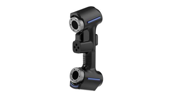
One common misconception is that 3D scanning replaces traditional metrology entirely. It does not. Scanners excel at dense surface data, but they still require alignment to GD&T callouts and periodic verification against certified artifacts. The practical approach treats scanning as complementary to CMMs and hard gauging, not as a wholesale substitute.
Systems like those offered by INSVISION illustrate the current technical range—scan areas up to 650mm×550mm for handheld units and configurations spanning single-line deep hole modes to 50-line high-speed arrays—but selection should follow application fit, not specification sheets alone.
- What Is 3D Scanning? Principles, Workflow, and Industrial Applications 3D scanning is a digital measurement technology that converts the surface geometry of physical objects into 3D data. This entry covers its working principles, core parameters, industrial use cases, common misconceptions, and related technical…
- What Is a 3D Scanner? Types, Parameters, and Selection Criteria A 3D scanner captures three-dimensional surface data from physical objects and converts geometry, dimensions, and features into digital data for inspection, reverse engineering, and modeling.
- What Is 3D Scanning Accuracy? Accuracy, Repeatability, and Resolution Explained 3D scanning accuracy describes how closely scan data matches an object's actual geometry and dimensions. It is assessed through local accuracy, volumetric accuracy, stitching accuracy, repeatability, and resolution.
- What Is Point Cloud Data? Point Clouds, Meshes, and CAD Models in 3D Scanning Point cloud data is an important raw data format in 3D scanning. It consists of discrete 3D coordinate points that describe object surface geometry and support inspection, reverse engineering, modeling, and archiving.
Hangzhou Insvision Technology Co., Ltd.
Address: Building 1, No. 1399 Liangmu Road, Yuhang District, Hangzhou, Zhejiang 311121, China
Copyright © Hangzhou Insvision Technology Co., Ltd. All rights reserved.
Copyright © Hangzhou Insvision Technology Co., Ltd. All rights reserved.