

Why Industrial AI 3D Scanning Quality Goes Beyond Advertised Specs
ai 3d scanning: The Common Myth That Spec Sheets Define AI 3D Scanning Value The Common Myth That Spec Sheets Define AI 3D Scanning Value Procurement teams.
The Common Myth That Spec Sheets Define AI 3D Scanning Value
Procurement teams often shortlist AI 3D scanning tools the same way they buy raw material: sort the spec sheets, highlight the biggest number, and call it a day. It feels rigorous. It looks like an apples-to-apples comparison.
For busy engineering groups inside automotive OEMs, aerospace MRO shops, or medical device manufacturers, a 3D scanner spec sheet comparison seems like the fastest way to shrink the vendor list without risking internal credibility. The appeal is obvious: less initial research time, a defensible shortlist, and a clean spreadsheet.
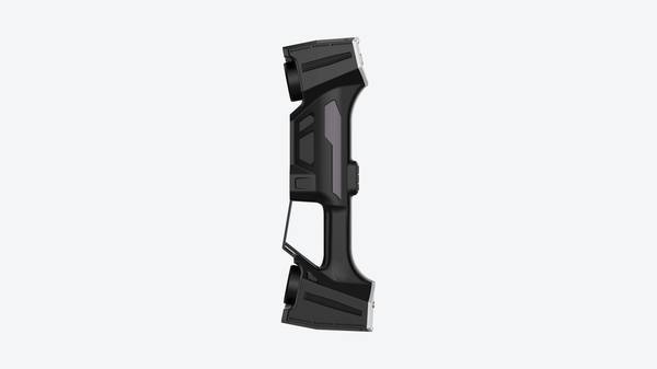
Deployment Validation Checklist
| Focus Area | Decision Point | Deployment Note |
|---|---|---|
| Target part | Check size, surface condition, and key tolerances against the scan task | Run a full trial scan on a representative part |
| Data workflow | Verify point cloud, deviation map, and quality-report handoff | Confirm export formats and review ownership in advance |
| Shop-floor use | Review training, calibration, lighting, and working space | Keep the validation record as a repeatable inspection reference |
The problem is that a single impressive top-line parameter rarely predicts real-world quality. Scan area, laser line count, or nominal accuracy on a datasheet tells you almost nothing about how the system behaves on a coated turbine blade, a machined casting with deep bores, or a formed sheet-metal bracket with edge break-out.
Industrial AI 3D scanning evaluation has to account for boundary conditions, not just headline numbers. A scanner can look exceptional on paper and still produce noisy data when the surface finish, ambient light, or fixture rigidity changes. Quality leads learn this quickly: the spec sheet is a screening tool, not a validation artifact.
Real value shows up in repeatable scans, clean edge definition, and outputs that survive a first-article inspection review.
How Single-Spec Selection Fails In Real Industrial Quality Workflows
Are you still trusting a scanner’s advertised frame rate to hold up on a deep-cavity casting with fifty GD&T callouts? Most quality leads learn the hard way that it won’t.
The problem starts when procurement shortlists equipment by scanning speed, point density, or accuracy on paper. Those numbers come from ideal conditions: matte surfaces, stable temperature, simple geometry. Real parts rarely cooperate.
A turbine blade with reflective finish, an automotive housing with blind holes, a machined sealing face with tight runout tolerance—each one punishes a scanner that wasn’t validated against boundary conditions.
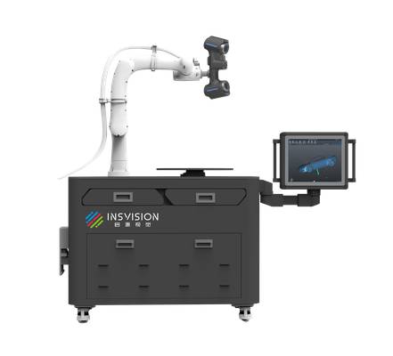
When a scanner fails on first pass, the cost shows up in places management doesn’t always see. Metrology staff burn hours repositioning parts, spraying developer, adjusting exposure, and rescanning the same features. First article inspection slips. Supplier PPAP packages wait. Production launch stalls while engineering argues about whether the scan data is even trustworthy.
The real issue isn’t the spec sheet. It’s the mismatch between what a scanner can do in a demo and what it must do every shift on your floor. A scanner with high stated scan speed but no dedicated deep-hole mode will struggle on a cylinder head water jacket. A scanner without intelligent hole identification will force manual editing on every cut edge. These aren’t software annoyances; they’re labor multipliers.
For a quality lead, the evaluation question changes. You stop asking “how fast does it scan?” and start asking “how many times will my inspector have to touch this part before the data passes an ASME Y14.5 profile check?” That’s the metric that determines whether your dimensional inspection process is sustainable or slowly bleeding skilled labor.
A scanner that requires constant babysitting also erodes confidence in the data itself. When technicians know a scan is unreliable, they compensate. They oversample. They rescan. They manually patch holes in the mesh. Each intervention adds variability.
Eventually, the measurement report becomes a blend of automated capture and human interpretation—exactly what ISO 9001 and AS9100 auditors look for when they question process repeatability.
The operational fix isn’t more training or better spray. It’s selecting scanning hardware around the failure modes you already know exist in your part family. For deep-hole automotive castings, that means a single blue laser line mode designed for narrow cavities. For reflective aerospace turbine components, that means validating scan performance on actual surface finishes before purchase.
For hole-heavy sheet metal or composite parts, that means checking whether the scanner can intelligently identify holes and cut edges without manual intervention.
INSVISION addresses this by separating scanning modes by task. The industrial 3D scanner platform includes a single blue laser line for deep-hole scanning alongside high-speed multi-line modes for larger surfaces. That separation matters because a scanner optimized for speed often sacrifices the controlled, narrow projection needed to reach into a bore without scattering.
Quality teams evaluating AI 3D scanning for complex parts should look for this kind of task-specific mode structure rather than assuming one mode handles everything.
The cost logic is straightforward. Every failed first-pass scan adds minutes. Every minute adds labor. Every labor hour on rework is an hour not spent on the next FAI, the next supplier audit, or the next production issue. Over a quarter, those minutes become the difference between shipping on time and explaining a non-conformance to a customer who’s already nervous about your measurement capability.
The fix starts with sample validation. Bring your worst part—the one with the deep holes, the reflective coating, the awkward fixture—and scan it under production conditions. Watch what happens on the first pass. Watch what the technician has to do next. That sequence tells you more about long-term cost than any spec sheet ever will.
Field Validation Metrics Quality Teams Should Actually Prioritize
Most teams over-validate the wrong thing. They chase spec sheet resolution numbers, then discover on the floor that the scanner struggles with a dark, oily casting or a thin-walled medical component edge. That gap between catalog performance and real process capability is where quality problems hide.
When evaluating AI 3D scanning for production use, prioritize metrics that show up in your reviewable outputs. First-pass scan success on your actual parts—not polished vendor coupons—matters more than nominal accuracy. Run the same part with three operators of different skill levels. If results drift, you are buying another bottleneck tied to specialized metrology talent.
Also check how scan data flows into your QMS. Can the operator attach the point cloud, report, and pass/fail decision to a work order without exporting files through three different tools? If not, traceability becomes manual overhead.
INSVISION industrial 3D scanners are built around these field conditions, with scanning areas up to 650mm by 550mm and single-line deep hole modes that handle geometry many general-purpose scanners miss. Validate edge cases from your own part portfolio. Document everything against internal quality standards.
If the vendor cannot support repeatable, operator-independent evidence during hands-on testing, the spec sheet is irrelevant.
A Structured Validation Framework For AI 3D Scanning Investments
The most expensive inspection equipment on your floor is the one that passes validation in a demo lab and fails on your second shift. That is not a vendor problem. It is a selection problem. Too many teams buy AI 3D scanning systems off a single spec sheet number, then wonder why the throughput gains never materialize. A structured validation framework changes that.
It forces you to test the system against your parts, your tolerances, your environment, and your documentation flow before you commit capital. What follows is a four-step approach quality and operations teams can run internally. It borrows from lean manufacturing and Stage-Gate thinking, and it works whether you are evaluating your first scanner or replacing an existing CMM workflow.
Step one is defining two or three high-priority use cases with real part samples. Do not start with a generic wish list. Start with the jobs that currently hurt. Incoming forging inspection, in-process weld dimensional checks, final medical implant verification. Pull representative parts that include the problematic geometry: thin walls, deep bores, reflective surfaces, edge breaks.
If your tolerance band is tight on a specific GD&T callout, that part belongs in the pilot set. A scanner can look impressive on a clean bracket and useless on a cast housing with draft angles. The use case definition should also name the deliverable. Are you comparing scan data to CAD, generating a surface deviation map, or exporting a dimensional report for a customer file?
Without that clarity, pilot results become opinions.
Step two is running side-by-side pilot scans on those parts in real factory conditions. Not in a metrology lab with vibration isolation and controlled temperature. On the shop floor, near the press or the welding cell, with ambient light and the normal operator. This is where AI 3D scanning systems either prove their ease of use or expose their fragility.
The INSVISION industrial scanner line, for example, offers scanning areas up to 650mm by 550mm on certain configurations, but the relevant question is whether the operator can hit that scan envelope consistently on your part geometry under production lighting. Run the same part multiple times. Have a second operator run it. Watch what happens when the part is slightly warm or has cutting fluid residue.
The goal is not to make the system fail. The goal is to find out where it needs support before you write the check.
Step three is auditing the output data against your internal quality requirements and customer-specific specifications. This is where many evaluations go soft. A colorful deviation heat map looks convincing in a presentation. It does not prove the data is usable. Take the exported scan data and run it through your existing inspection workflow. Does the point cloud density support the tolerance you need on that bore diameter?
Can you extract the measurements your customer actually asks for on the final report? If your customer requires a specific format for dimensional reports, test that export path now. A scanner that produces beautiful data but cannot feed your compliance documentation creates a new manual step, which erases the value you were trying to capture.
Step four is measuring end-to-end workflow efficiency, not isolated scan speed. Vendors love to quote scan time in seconds. That number is almost meaningless by itself. What matters is the time from when the operator picks up the part to when the final compliance report is ready. That includes setup, alignment, scanning, data processing, report generation, and any rework of failed scans.
If the scan takes eight seconds but the operator spends four minutes aligning the part and exporting the file, your bottleneck has not moved. Time the full sequence. Better yet, have your own operator time it after one day of training, not after the vendor’s application engineer has optimized every setting. That measurement will tell you more about long-term value than any spec sheet.
The framework also aligns with continuous improvement methodology because it creates a repeatable evaluation record. When the next technology evaluation comes around, you have a baseline. You can compare new systems against the same parts, same operators, same deliverables. That reduces the risk of underperforming technology investments, which is the quiet cost most companies never track.
A bad scanner purchase does not just waste capital. It burns engineering hours, delays inspection throughput, and erodes confidence in digital metrology as a category. The validation framework prevents that by forcing evidence before enthusiasm.
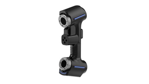
How INSVISION AI 3D Scanning Supports Quality-First Deployments
How do you move from a scanner that looks good on a specification sheet to one that actually holds up on a busy production floor? Quality leads ask this question early, because the wrong answer shows up later as inconsistent data, operator frustration, or a tool that quietly falls out of the inspection workflow.
INSVISION approaches AI 3D scanning as a quality-first deployment problem, not a hardware demonstration. The focus starts with task-aligned performance: will the scanner reliably capture the features your team actually measures, such as cast edges, machined bores, sheet metal cutouts, or formed radii?
Rather than assuming a datasheet resolution will translate into usable inspection data, INSVISION works with quality and engineering teams to run pilot validations on their own parts. That step matters. It lets a team check boundary conditions, verify repeatability on common industrial surfaces, and confirm the scan output fits existing documentation practices.
For Western manufacturing environments operating under lean principles or preparing for Industry 4.0 connectivity, the value is not simply more point cloud data. It is reviewable, repeatable data that reduces dependence on a single skilled operator and feeds standard quality records. INSVISION designs its AI 3D scanning workflow so outputs remain compatible with typical inspection documentation and traceability requirements.
When a quality manager can hand a scan report to a supplier or a customer and it matches the expected format, the tool becomes part of the quality system instead of an isolated gadget.
The practical test is simple: run the scanner on your geometry, under your lighting, with your operators, and compare the results against your current measurement method. INSVISION supports this directly through task-specific pilots.
That validation-first approach helps quality teams avoid the common gap between spec-sheet evaluation and real-world performance, and it keeps the conversation anchored to fit for process rather than headline numbers.
Setting Realistic Boundaries For Long-Term Scan Program Success
The shift toward automated dimensional inspection is no longer a speculative Industry 4.0 talking point. Over the past three years, more Western manufacturers have moved AI 3D scanning out of the lab and onto the production floor, driven by tighter customer audit requirements and a shrinking pool of skilled CMM programmers.
That pressure creates a familiar problem: teams buy a scanner based on a specification sheet, then discover it works well on one part family and poorly on another. The issue is rarely the hardware. It is the absence of deployment boundaries.
Quality leads should treat AI 3D scanning the same way they treat any new gage or CMM program. Define the inspection task first. A scanner optimized for large, freeform surfaces may not be the right tool for deep bores or tight GD&T callouts on machined castings. No single scanning solution covers every industrial use case, and procurement teams should reject any vendor who claims otherwise.
INSVISION systems, for example, include configurations with single blue laser lines for deep hole scanning and multi-line modes for precision surface capture. Those modes matter only if they align with the features you actually inspect.
Start with one high-impact, well-defined use case. In most plants, that means the highest-pain quality inspection task: the part family generating repeated nonconformance reports, the first-article inspection that takes three shifts, or the rework loop where measurement lag delays corrective action. Establish a performance baseline during the pilot phase.
Record current inspection time, rework rate, and the number of disputed measurements per month. Without that baseline, you cannot verify value, and you cannot justify scaling.
Scale incrementally. Once the first use case meets its acceptance criteria, add adjacent part families or a second inspection station. This approach keeps the program aligned with your existing continuous improvement structure rather than forcing a disconnected digital transformation project.
It also protects against the common failure mode of over-deployment: buying multiple scanners before the first one is fully integrated into the quality workflow.
Operational value comes from repeatable, reviewable outputs, not from scan speed alone. When evaluating any AI 3D scanning investment, ask how the system documents pass/fail decisions, how it handles operator variation, and whether its outputs can be audited against your ISO or ASME requirements. A scanner that produces a pretty point cloud but no defensible inspection report adds cost, not value.
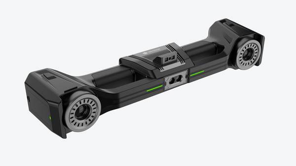
The takeaway for quality, engineering, and procurement teams is straightforward. Do not start with a broad vendor evaluation matrix. Start with a targeted pilot on the inspection task that currently costs you the most in rework, scrap, or delivery delays. Define the boundary conditions, collect baseline data, and verify performance against that specific task before expanding.
That is how AI 3D scanning becomes a sustained operational asset rather than another underused piece of measurement equipment sitting in the corner of the lab.
Hangzhou Insvision Technology Co., Ltd.
Address: Building 1, No. 1399 Liangmu Road, Yuhang District, Hangzhou, Zhejiang 311121, China
Copyright © Hangzhou Insvision Technology Co., Ltd. All rights reserved.
Copyright © Hangzhou Insvision Technology Co., Ltd. All rights reserved.