

Why 3D Laser Triangulation Single-Spec Claims Mislead Quality Teams
3d laser triangulation: The Widespread Assumption That a Single Accuracy Spec Defines 3D Laser Triangulation Performance Why do so many capable quality teams.
The Widespread Assumption That a Single Accuracy Spec Defines 3D Laser Triangulation Performance
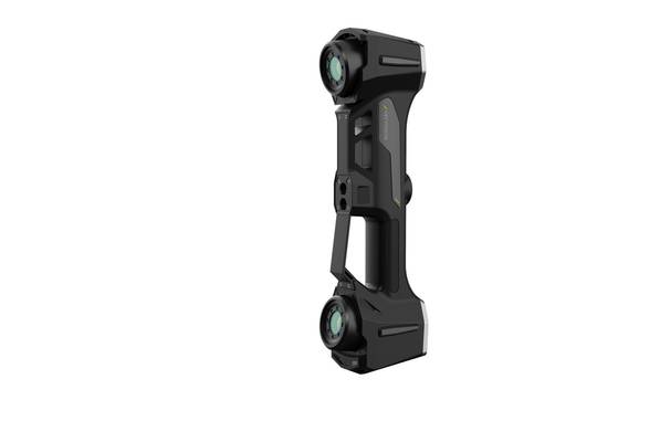
Why do so many capable quality teams still end up with a 3D scanning system that misses expectations on the floor? The answer often traces back to a single shortcut: shortlisting 3D laser triangulation equipment by one top-line accuracy figure from a vendor datasheet.
Deployment Validation Checklist
| Focus Area | Decision Point | Deployment Note |
|---|---|---|
| Target part | Check size, surface condition, and key tolerances against the scan task | Run a full trial scan on a representative part |
| Data workflow | Verify point cloud, deviation map, and quality-report handoff | Confirm export formats and review ownership in advance |
| Shop-floor use | Review training, calibration, lighting, and working space | Keep the validation record as a repeatable inspection reference |
During PPAP preparation for an automotive OEM launch, or while assembling AS9102 first-article documentation for an aerospace component, lean teams face tight deadlines and limited staffing. Scanning through spec sheets and circling the lowest micron number feels efficient. But that number rarely survives contact with real parts, real surface finishes, and real measurement routines.
The assumption that one accuracy spec defines system performance is not just optimistic; it creates costly gaps between quoted capability and actual inspection behavior on production geometry. This section unpacks why that single-spec approach falls short, what boundary conditions actually drive 3D laser triangulation performance, and how quality teams can validate systems against their own production needs before committing.
Why Datasheet-Only 3D Laser Triangulation Evaluations Fail on the Shop Floor
Are you comparing 3D laser triangulation sensors by spec sheet alone? That approach rarely survives first contact with a real production line.
Key Points at a Glance
- Are you comparing 3D laser triangulation sensors by spec sheet alone?
- Most quality teams treat a new 3D laser triangulation scanner like a lab instrument.
- A quality engineer pulling a first-article sample off the line rarely cares about a scanner’s marketing spec sheet.
- A quality engineer walking a stamping line in Michigan or an aerospace MRO cell in Wichita does not need another datasheet.
The core principle is straightforward. A laser projector casts one or more lines onto a part surface. One or more offset cameras capture the distorted line profile. On-board processing applies trigonometric triangulation to calculate precise 3D coordinates for every point along that line. The offset angle between laser and camera determines resolution and measurement range.
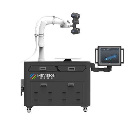
Lab specs, however, assume idealized conditions. Real parts introduce variables that datasheets simply cannot capture. Shiny aluminum reflects laser energy away from the camera. Carbon fiber composite absorbs it unevenly. Translucent medical plastics scatter light below the surface, smearing the profile.
These surface properties alone can shift accuracy by orders of magnitude compared to the matte calibration artifact used in the vendor’s test lab.
Part geometry compounds the problem. Deep holes, undercuts, and fine edge features may be partially or fully obscured from the camera’s field of view. What the camera cannot see, the algorithm cannot measure. A sensor that performs flawlessly on a flat gauge block may miss critical features on a cast housing or machined bracket.
Operating environment adds another layer. Shop floor vibration from stamping presses or CNC spindles introduces micro-motion between sensor and part. Overhead LED fixtures can saturate the camera sensor at certain wavelengths. Temperature swings of ten degrees can shift optical alignment enough to invalidate a tight tolerance measurement. These variables rarely appear in a single datasheet spec.
Measurement volume matters too. Accuracy is often quoted at the center of the scan volume, where the triangulation angle is optimal. Move toward the edges and accuracy degrades. A sensor rated at 0.02 mm at center might deliver 0.05 mm at the volume boundary. If your inspection routine covers that full volume, the quoted number misleads.
The result? Quality teams discover these gaps during first-article inspection or production launch. Rework follows. Audit findings pile up. Launch dates slip.
INSVISION addresses this through application-focused validation rather than spec-sheet selling. The right evaluation starts with your actual parts, your surface finishes, your lighting conditions, and your required GD&T callouts. Datasheets inform. Boundary conditions decide.
Actionable Field Validation Steps for Auditable 3D Laser Triangulation Performance
Most quality teams treat a new 3D laser triangulation scanner like a lab instrument. They request a demo, scan a couple of calibrated gauge blocks, and call it validated. That is a mistake. Gauge blocks are smooth, bright, and geometrically simple. Production parts are not.
If your validation plan does not account for real surface finishes, shop floor vibration, and the full measurement volume, you are not validating the scanner. You are validating a clean-room scenario that will never occur in production.
INSVISION scanners are built for industrial environments, but even the best hardware will fail downstream if the validation framework is weak. The steps below are structured around ISO 17025 traceability and ASME Y14.5 GD&T requirements, with one goal: produce audit-ready evidence that the scanner performs where you actually inspect parts.
Every step should generate documentation you can hand to a customer auditor without hesitation.
Start with representative production parts, not gauge blocks. Pick three to five parts that include the full range of surface finishes, geometries, and critical features your team inspects regularly. Include a rough cast surface, a machined face, a deep pocket, and a thin wall if those appear in your production mix. Scan each part multiple times and compare the scanner output to your existing CMM or manual inspection data.
Document deviations on specific GD&T callouts, not just overall dimensional error. A scanner can hold tight tolerance on a flat surface and fail completely on a sharp edge or a reflective burr. You need to know that before procurement.
Run a Gage R&R study on the shop floor, not in a metrology lab. Temperature swings, ambient light, vibration from nearby presses, and operator variation all affect 3D laser triangulation performance. Use two or three operators, ten representative parts, and three repeated measurements per operator. Calculate percent GRR against your tolerance band.
For most automotive, aerospace, and medical device suppliers, anything above 30 percent is a red flag. Between 10 and 30 percent may be acceptable depending on the feature criticality. Below 10 percent is ideal. Document the environmental conditions during the study. Auditors will ask.
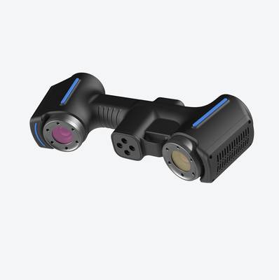
Validate performance across the full measurement volume. Many scanners perform well in the center sweet spot and degrade noticeably near the edges of the field of view. If you inspect large stampings, castings, or welded assemblies, you need consistent results across the entire scan envelope.
Place a calibrated artifact or a representative part at multiple positions within the measurement volume, including the corners and near the maximum working distance. Compare the results. A scanner that requires you to keep every feature dead center is not practical for production use.
Confirm data output compatibility with your existing quality workflow before signing anything. The scanner may produce excellent point clouds, but if those point clouds cannot flow into your CAD comparison software, SPC tools, or PLM system without manual conversion steps, you are buying a bottleneck. Ask for a raw data export during the validation. Open it in your current software.
Check that the coordinate system, units, and feature naming conventions survive the transfer. Integration delays are one of the most common reasons new scanning equipment sits unused after purchase.
All of this ties directly to Industry 4.0 smart quality goals. Traceable, data-driven inspection processes require more than a good sensor. They require a documented chain of evidence from scan data to final report. Every validation step above should produce a dated, signed record that links the scanner serial number, software version, environmental conditions, and operator to the results.
That is what makes the process auditable. INSVISION supports this by providing scan data in formats that integrate with standard quality software, but the validation framework belongs to your quality team. Build it before procurement, not after.
How INSVISION 3D Laser Triangulation Solutions Support Production-First Validation
A quality engineer pulling a first-article sample off the line rarely cares about a scanner’s marketing spec sheet. What matters is whether the system will hold up on the shop floor, produce repeatable data against existing GD&T callouts, and integrate without forcing a rewrite of the inspection workflow. In a lean manufacturing environment, validation happens on real parts, under real conditions, before capital is committed.
That is the lens through which INSVISION approaches industrial 3D scanning.
INSVISION builds its industrial scanner category around 3D laser triangulation, a measurement principle that has become standard in metrology-grade surface inspection. The technology projects a laser line or pattern onto a part, observes the deformation through a calibrated camera, and reconstructs surface geometry point by point.
It is fast, non-contact, and capable of resolving fine features on castings, machined surfaces, and molded components. But the principle itself is not the differentiator; implementation is.
The practical concern for quality teams is boundary conditions. How does the scanner behave on shiny or dark surfaces? What happens when ambient light changes near a machining cell? How much operator judgment is required to get a clean scan? INSVISION addresses these questions through configurable scanning settings rather than a single fixed mode.
Teams can adjust scanning density, exposure, and acquisition speed to match the inspection task. A dimensional check on a sealing groove might call for fine feature resolution, while a high-throughput surface scan on a stamped panel prioritizes speed. The same hardware supports both, but the user controls the trade-off.
This matters because validation is not a one-size-fits-all exercise. A first-article inspection on a machined aerospace bracket has different requirements than incoming inspection on a plastic housing. INSVISION scanners are designed to handle common industrial part types across those scenarios, with settings that let quality engineers define the acceptable balance between point density and cycle time.
The output is structured point cloud data that can be compared against CAD models or used for surface deviation mapping.
The more important part of the validation story is sample-based testing. INSVISION does not ask buyers to trust a datasheet. Quality teams can supply their own production parts, define the inspection criteria, and receive documented results that map directly to their GD&T requirements. That is a traceable, reviewable deliverable.
It allows an engineer to see how the scanner handles a specific edge break, a counterbore, or a freeform surface before signing off on the purchase. Post-purchase rework risk drops when the system has already demonstrated performance on the parts that will actually run through it.
From a lean manufacturing perspective, this approach supports faster deployment. The time spent validating on real samples is time saved later during integration. When the scanner arrives, the inspection templates and settings are already understood. There is less trial-and-error on the floor, fewer surprises during first-article runs, and a cleaner handoff to existing digital quality workflows.
That is the practical value of a production-first validation model: evidence before purchase, not after.
Practical Boundaries for 3D Laser Triangulation in Industrial Quality Workflows
A quality engineer walking a stamping line in Michigan or an aerospace MRO cell in Wichita does not need another datasheet. What they need is a straight answer: will this scanner hold up on my part, under my lighting, with my surface finish, and deliver data my CMM correlation will accept?
The assumption that a single 3D laser triangulation device can replace every gage, profilometer, and vision system in the plant is still surprisingly common. It is also expensive when it goes wrong.
3D laser triangulation works by projecting a laser line onto a surface, capturing the deformed line with a camera at a known angle, and calculating height from the lateral shift. It is fast, non-contact, and dense. But it is not universal. The boundaries are set by physics, not software.
Where 3D laser triangulation earns its place is in mid-scale, diffuse, production-relevant geometry. Automotive body panel gap and flush inspection, stamped part dimensional compliance, and PPAP first article checks are strong fits. The surfaces are typically matte enough, the tolerances align with scanner resolution, and the deliverable is a point cloud or color map that a supplier can review against GD&T callouts.
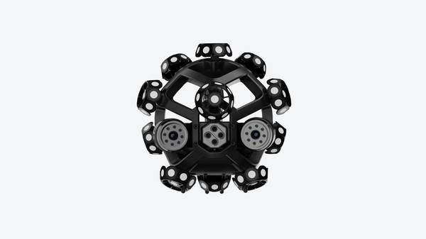
Aerospace MRO follows the same logic. Composite part surface inspection, damage assessment on airfoils, and tooling verification all involve shapes where dense surface data beats single-point probing. Medical device teams use 3D laser triangulation for implant dimensional validation and injection molded part quality checks, particularly when the alternative is slow, operator-dependent manual gaging.
General manufacturing rounds out the picture. Reverse engineering of machined parts and tool wear monitoring benefit from the ability to capture full geometry quickly and compare it to a nominal CAD model. In these workflows, the scanner is not replacing a CMM. It is reducing the number of parts that need to go to the CMM.
The boundary appears when the part geometry or material fights the laser. Ultra-fine micro-scale features below the scanner’s practical resolution, highly reflective mirrored surfaces that scatter the line unpredictably, and fully transparent materials that do not return a usable signal all require sample validation before committing to a scanning workflow. This is not a product limitation specific to INSVISION.
It applies to the entire category of laser triangulation devices.
Quality leads should treat sample validation as a gate, not a formality. Send a representative part. Scan it under production lighting. Compare results to the existing measurement method. If the correlation is acceptable, the investment is defensible. If it is not, the team has saved itself from a costly mismatch.
INSVISION industrial 3D scanners fit into this evaluation framework because the category itself is well suited to the use cases above. For teams working with diffuse surfaces, production tolerances, and a need for reviewable point cloud outputs, the technology is mature. For teams chasing the highest single datasheet number, that is usually the wrong question.
The right question is whether the scanner matches the part, the tolerance, and the workflow.
Common 3D Laser Triangulation Validation Questions Quality Teams Ask
The shift toward inline dimensional inspection has surfaced a recurring set of questions from quality engineers who are evaluating 3D laser triangulation for the first time. The answers rarely fit neatly into a spec sheet.
Q: Is a higher laser line count always better for 3D laser triangulation accuracy?
No. Line count primarily affects scanning speed and coverage area, not measurement accuracy. Accuracy depends on optical calibration quality, surface finish, and feature geometry. A scanner with 50 blue laser lines can cover a large surface quickly, but it will not necessarily resolve a tight GD&T callout better than a 7-line precision mode.
Quality teams should validate performance on their own parts, using their own tolerances, rather than using line count as a proxy for accuracy.
Q: Can 3D laser triangulation scanners be used on the shop floor, or do they require a controlled lab environment?
Many industrial-grade systems are built for shop floor deployment, but real-world consistency depends on vibration damping, ambient light shielding, and temperature stability. A scanner that performs well in a metrology lab may behave differently next to a stamping press. The only reliable way to verify is on-site sample testing in the actual workspace.
Pay attention to whether the system maintains repeatability across a full shift and under changing ambient conditions.
Q: Does a higher laser safety class mean lower 3D laser triangulation precision?
Laser class is a safety specification tied to maximum output power and eye exposure risk. It is not a precision metric. INSVISION industrial 3D scanner line, for example, uses Class II eye-safe lasers for handheld operation, while other configurations may use different classes depending on the application.
Teams should validate accuracy independently of safety class and select a system that meets both their measurement requirements and their site safety policies.
The common thread across these questions is the same: evidence on your parts, in your environment, under your constraints. Generic spec comparisons do not answer these questions. Part-specific validation does.
Hangzhou Insvision Technology Co., Ltd.
Address: Building 1, No. 1399 Liangmu Road, Yuhang District, Hangzhou, Zhejiang 311121, China
Copyright © Hangzhou Insvision Technology Co., Ltd. All rights reserved.
Copyright © Hangzhou Insvision Technology Co., Ltd. All rights reserved.