

What Manufacturers Should Check Before Choosing 3D scanning inspection
3d scanning inspection: Quality Inspection Bottlenecks in Modern Discrete Manufacturing Is your CMM queue the reason first-article approval slips another.
Quality Inspection Bottlenecks in Modern Discrete Manufacturing
Is your CMM queue the reason first-article approval slips another shift? That question surfaces constantly in discrete manufacturing plants, especially where high-mix low-volume work has become the default. Quality teams juggle touch-probe programs that cannot keep pace with changeover frequency. Process engineers wait on dimensional data before adjusting offsets.
Meanwhile, suppliers and internal cells argue over which critical features actually matter because the drawing interpretation differs across shifts. The result is predictable: rework, expedited metrology, and late verification.
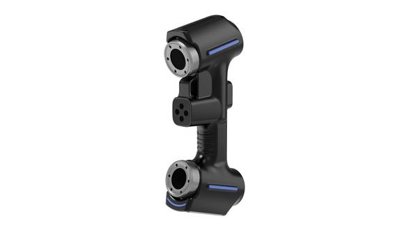
Selection Dimensions and Field Checks
| Focus Area | Decision Point | Deployment Note |
|---|---|---|
| Quality Inspection Bottlenecks in Modern Discrete Manuf… | Is your CMM queue the reason first-article approval slips another shift? | That question surfaces constantly in discrete manufacturing plants, especially where high-mix low-volume work has become the default. |
| Pre-Inspection Preparation for Reliable 3D Scan Data | Most people assume a 3D scanning inspection failure starts at the scanner. | It rarely does. |
| On-Station Scan Capture: Path Planning and Feature Cove… | Before 3D scanning inspection moved onto the shop floor, a machined casting or welded assembly often sat in a queue waiting for a CMM fixture or a ma… | The inspection itself was not the bottleneck. |
| Point Cloud Processing and Deviation Analysis Workflow | Most people assume a 3D scanner spits out an inspection report. | It does not. |
3D scanning inspection has moved into the gap. It is not a wholesale replacement for CMMs, but it changes where and how quickly dimensional questions get answered. In automotive component validation, aerospace MRO checks, and medical device part inspection, the workflow now often starts with a full-field scan, proceeds to a color map against CAD or a reference mesh, and reserves contact metrology for the tighter callouts.
ISO and ASME frameworks still govern the acceptance criteria. The data collection method simply becomes faster and denser.
This article walks through the cross-functional workflow: how quality, manufacturing, and design teams hand off scan data, review exceptions, and verify results without turning every dimensional question into a CMM backlog item. The intent is to help you evaluate whether 3D scanning inspection fits your specific use cases, not to argue that it fits all of them.
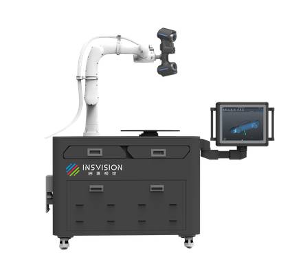
Pre-Inspection Preparation for Reliable 3D Scan Data
Most people assume a 3D scanning inspection failure starts at the scanner. It rarely does. The scanner only captures what the station presents to it. If a part is fixtured in a way that blocks a critical datum feature, or if a reflective surface scatters the laser return, the resulting mesh will carry that error into every downstream comparison. No amount of software filtering recovers data that was never captured.
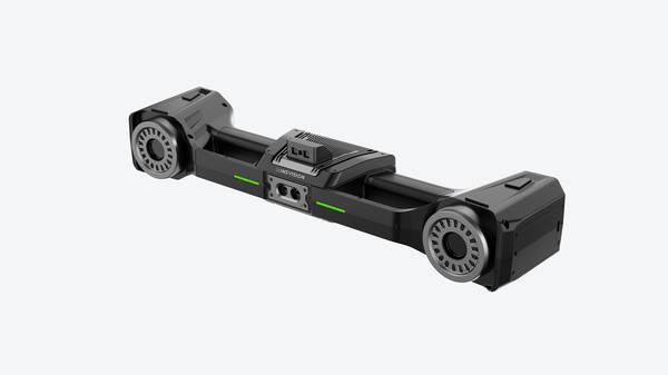
Pre-scan preparation is where production and quality teams actually align. The goal is simple: make the first scan the valid scan. That means checking three things before the scanner powers on. First, part fixturing must hold the component rigidly without obscuring high-priority inspection features. A fixture that covers a machined bore or a sealing face forces a rescan or, worse, hides a defect entirely.
Second, surface preparation matters more than many shops expect. Reflective or translucent components need a temporary matte coating, typically a fine titanium dioxide or similar spray, to return a stable point cloud. Third, reference marker placement should follow the GD&T callouts on the drawing. Markers placed randomly will not anchor the scan to the datums that control the tolerance stack-up.
The handoff between teams is where errors creep in. A production lead may release a part assuming the quality tech knows which features are critical. The quality tech may assume the part arrived ready to scan. A formal pre-scan sign-off removes that ambiguity. It does not need to be a heavy document. A one-line checklist confirming inspection scope, critical tolerances, and surface condition is enough.
The point is that both sides agree on what the scan must prove before data collection begins.
This discipline pays off quickly. Standardized 3D scanning inspection preparation eliminates repeat scans, reduces downstream data processing errors, and makes results repeatable across shifts. When a second operator runs the same part on a different day, the setup should produce comparable data.
That is the difference between a scanning station that supports quality decisions and one that generates pretty but unreliable pictures.
INSVISION scanners are built for this kind of workflow because they tolerate real shop conditions. Blue laser projection, as used across the INSVISION product range, performs better than red laser on many reflective and dark surfaces, but it does not remove the need for proper preparation. Accurate 3D scan data best practices still start at the fixture, not the lens. The scanner amplifies good setup.
It cannot correct bad input.
For Western manufacturers working under ASME Y14.5 or ISO GPS rules, this matters. A scan report that cannot be tied back to a datum reference frame is not an inspection record. It is a visualization. Production and quality teams that treat pre-scan preparation as a formal station task, rather than a casual warm-up, get data they can defend in a first-article review or a customer audit. That is the whole point.
On-Station Scan Capture: Path Planning and Feature Coverage
Before 3D scanning inspection moved onto the shop floor, a machined casting or welded assembly often sat in a queue waiting for a CMM fixture or a manual surface plate layout. The inspection itself was not the bottleneck. The wait was. Now the workflow difference is visible at the station: an operator can fixture a part, capture full geometry, and release it before the next operation finishes.
But that speed only holds when the scan path is planned around the features that actually drive acceptance.
Operators and quality engineers approach the same scan from two directions. The operator wants minimum handling, stable reference targets, and a scan that runs clean the first time. The quality engineer wants dense point coverage on tight-tolerance callouts, complete data on datum features, and enough overlap between passes to support alignment.
Both concerns have to be resolved before the scan starts, not after the point cloud is already open.
Effective 3D scan path planning starts with a simple question: which features will be reported? If the drawing flags a bore position at ±0.05 mm and a surface profile at ±0.25 mm, those zones do not receive equal treatment. The path should dwell longer on the bore, approach it from multiple angles, and capture the full cylinder rather than a partial arc. The large flat surfaces can be captured quickly in a single pass.
This is the difference between a scan that merely covers the part and a scan that actually supports dimensional decisions.
Scanning mode selection follows the same logic. Deep holes and counterbores are difficult for wide-area laser patterns because the geometry shadows itself. A single blue laser line gives the sensor a better chance to reach into the cavity and return usable data. Sharp edge profiles need higher resolution passes to define the transition between surfaces.
Large areas benefit from multi-line or high-speed patterns that reduce station time. In practice, a well-planned scan uses two or three modes on the same part: fast acquisition for the body, targeted precision for critical features, and a narrow line for recessed geometry.
For operators running the station, coverage verification happens before the part leaves the fixture. That means reviewing the live scan data for gaps, thin areas around edges, or missing patches inside holes. If the software shows a hole with no interior data, that is not a question to resolve later in the quality report. It gets rescanned now, while the part is still fixtured and the reference markers are stable.
INSVISION industrial 3D scanners support this type of flexible scanning configuration because the sensor can shift between rapid full-part scans and targeted high-precision capture without moving the part to a second station.
Quality engineers typically define a minimum coverage rule for critical features. The rule might state that every tight-tolerance bore must show complete interior scan data, and every datum plane must be captured across at least three non-collinear regions. These rules are not theoretical. They prevent the most common inspection failure mode: a good alignment built on incomplete data.
Reference markers also influence path planning. Parts with large smooth surfaces may need additional targets placed before scanning begins. The operator’s path should avoid blocking those targets during the scan. On complex parts, markers placed on raised bosses or adjacent fixture plates often improve alignment stability more than markers placed on the part surface itself.
This is the kind of station-level detail that separates repeatable 3D scanning inspection from a one-off demonstration.
The handoff from scan station to quality review is now cleaner. Instead of re-measuring a suspect feature days later, the operator and engineer resolve coverage gaps in real time. The result is fewer exceptions in the final report and less rework caused by incomplete inspection data.
3D scanning inspection feature coverage, when treated as a station discipline, shortens the loop between machining and release without adding inspection labor.
Point Cloud Processing and Deviation Analysis Workflow
Most people assume a 3D scanner spits out an inspection report. It does not. The scanner produces a point cloud — millions of XYZ coordinates with no inherent understanding of what is a surface, a hole, or a datum. Everything downstream depends on what happens between scan acquisition and deviation reporting. That handoff is where inspection programs either catch real process drift or drown in false flags.
Point cloud processing for industrial inspection starts with cleaning. Scan operators remove stray reflections, edge artifacts, and fixture geometry before the data ever reaches a quality engineer. Noise removal is not cosmetic; residual noise inflates deviation values and creates phantom out-of-tolerance conditions. Once cleaned, the point cloud is aligned to nominal CAD using best-fit or datum-based registration.
For legacy parts without CAD, operators can register against reference scan data from a known-good part. Alignment method matters more than most teams admit. A best-fit on a flexible casting will hide form error that a datum-constrained alignment would expose.
After alignment, GD&T callouts drive the analysis. Position tolerances, profile tolerances, runout — each maps to specific point cloud regions. The software then generates color-coded deviation heatmaps, with green zones inside tolerance and red zones flagged for review. Flagged features enter a collaborative exception workflow.
Quality engineers pull process teams into the review early, comparing deviation patterns against tool wear, clamping pressure, or upstream machining offsets. Catching a 0.15 mm drift on feature twelve does not just reject one part; it prevents the next hundred from being machined wrong.
For parts with no CAD, the same processed point cloud feeds reverse-engineered models usable for both inspection and future production. INSVISION scanners support scanning areas up to 650 mm × 550 mm on industrial 3D scanner-class systems and up to 2200 mm × 2200 mm on the industrial 3D scanner, covering everything from small castings to large fabricated assemblies.
The key is not scan speed — it is that the point cloud processing and 3D scanning deviation analysis workflow keeps scan operators and quality engineers speaking the same data language before a single part reaches formal disposition.
Inspection Deliverables and Traceability for Cross-Team Alignment
Are your quality, production, and customer-facing teams actually looking at the same part data? In many Western manufacturing environments, the gap is not measurement capability. The gap is the handoff between the scan, the report, and the downstream decision.
Inspection deliverables from 3D scanning inspection need to do more than flag a pass or fail. A useful workflow produces an ISO/ASME-compliant inspection report with color-mapped deviation data against the nominal CAD model. For legacy components with no CAD, the same scan data feeds reverse-engineered CAD files.
Structured point cloud and mesh storage then preserves full part traceability without forcing your QMS to adopt a new database.
Visual deliverables reduce the back-and-forth. A quality engineer, a production supervisor, and a customer-facing program manager can review the same deviation map and agree on disposition. That is especially relevant for aerospace AS9102 FAI reports, automotive PPAP documentation, and medical device traceability records where 3D inspection traceability standards are non-negotiable.
INSVISION scanners support this by capturing dense surface data that converts directly into repeatable 3D scanning inspection reporting, not just a table of numbers.
Reinspection Triggers and Common 3D Scanning Inspection Questions
Why should a quality team plan for reinspection before the first scan even happens? In a production environment, one 3D scanning inspection report rarely closes the loop. The real value shows up when scan data drives a process decision, and that usually means scanning again after something changed.
Post-rework validation is the most obvious trigger. When a machined casting or weldment is corrected based on an initial scan, the same 3D scanning inspection routine should run again on the reworked area. This confirms the fix worked and gives you a measurable before-and-after record. Scheduled tooling wear checkpoints work differently.
Instead of waiting for dimensional drift to show up in final inspection, teams scan parts at planned intervals to catch die wear, mold degradation, or fixture shift before it produces scrap. Batch variation alerts follow a similar logic. If an upstream material lot or process parameter changes, a quick scan of first-off parts in the new batch can flag deviations early.
Corrective action verification then ties all of this together. After an 8D or CAPA process identifies a root cause, a follow-up 3D scanning inspection verifies that the corrective action actually changed the dimensional outcome, not just the paperwork.
Each of these triggers supports a closed-loop quality model that fits cleanly into Industry 4.0 thinking. Scan data becomes process feedback, not just a pass-fail gate.
One question that comes up repeatedly is whether 3D scanning inspection can replace a CMM on tight-tolerance parts. The honest answer depends on the tolerance band, the feature geometry, and how the measurement system is validated against your specific requirements.
Structured light and laser scanning generate dense point clouds that are excellent for form, profile, and comparative analysis, but a tactile CMM may still be preferred for certain tight positional callouts or highly reflective surfaces. Teams should run GR&R studies and compare results against their existing CMM baseline before making that call.
Deep holes and internal features present a different challenge. Line-of-sight optical systems cannot capture what they cannot see. That is why some INSVISION industrial 3D scanner configurations include a single blue laser line mode for deep hole scanning. This mode helps reach into recessed areas that broader multi-line patterns struggle to cover.
Still, very deep, narrow bores or hidden internal cavities may require sectioning, borescope assistance, or a different measurement approach altogether.

Standards questions also come up frequently. The applicable standard depends on what the scan output is used for. First-article inspection under ASME Y14.5, ISO GPS geometry reporting, or industry-specific requirements like aerospace MRO documentation all carry different expectations for data traceability, alignment methods, and reporting formats.
Teams should validate their 3D scanning inspection workflow against the standard that governs their specific part class and end use. INSVISION partners with quality teams to align scan workflows with applicable standards and internal quality protocols, rather than assuming a generic scan report satisfies every compliance requirement.
Hangzhou Insvision Technology Co., Ltd.
Address: Building 1, No. 1399 Liangmu Road, Yuhang District, Hangzhou, Zhejiang 311121, China
Copyright © Hangzhou Insvision Technology Co., Ltd. All rights reserved.
Copyright © Hangzhou Insvision Technology Co., Ltd. All rights reserved.