

3D scan object: Principles, Parameters, and Use Cases
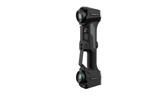
3d scan object: What Is 3D Scan Object? What Is 3D Scan Object? 3D scan object refers to the non-contact capture of three-dimensional surface data from a.
What Is 3D Scan Object?
What Is 3D Scan Object?

3D scan object refers to the non-contact capture of three-dimensional surface data from a physical part using structured light, laser triangulation, or photogrammetry. The output is a dense point cloud or polygon mesh that serves as a digital twin of the as-built geometry. In industrial settings, this process differs fundamentally from consumer-grade scanning.
Industrial systems must deliver repeatable, traceable measurements — not just visually recognizable shapes.
The key distinction is metrological alignment. Industrial 3D object scanning workflows are validated against ISO 10360 acceptance and reverification tests for coordinate measuring systems. That means volumetric accuracy, probing error, and scanning error are quantified and documented, not assumed.
A handheld scanner that produces a smooth-looking mesh is not the same as a system that holds ±0.020 mm accuracy across a defined working volume.
In Western manufacturing, 3D object scanning functions as a bridge between physical parts and digital engineering workflows. Quality teams use it for first-article inspection, where scanned point clouds are compared directly to CAD nominal geometry using GD&T callouts per ASME Y14.5.
The deviation color maps show exactly where a part drifts out of tolerance — flatness, profile, position, runout — without the setup time of traditional CMM probing.
| Criteria | Industrial 3D Object Scanning | Consumer 3D Scanning |
|---|---|---|
| Accuracy standard | ISO 10360 verified | Manufacturer claim, often unverified |
| GD&T workflow support | Yes — deviation analysis against CAD | No — mesh visualization only |
| Data repeatability | Documented, traceable | Variable, environment-dependent |
| Application focus | Inspection, reverse engineering, MRO | Hobby, prototyping, visualization |
| Output integration | MES, SPC, PLM systems | Standalone files |
For lean quality control, the advantage is speed without sacrificing data density. A single scan captures millions of points across a surface, whereas tactile probing captures discrete points one at a time. That data density matters when evaluating complex freeform surfaces or thin-wall deflection.
Industry 4.0 initiatives push this further: scan data feeds directly into digital twin repositories, enabling trend analysis across production batches and faster root-cause investigation when dimensional drift appears.
Equipment selection hinges on several factors. Laser class matters for operator safety in open production cells — Class II systems are eye-safe under normal operating conditions. Depth of field determines how much geometry variation a scanner can capture without repositioning. Working temperature range affects performance on shop floors that lack climate control. Output formats must integrate with existing inspection software;
STL and PLY are common exchange formats, but some workflows require native point cloud export.
INSVISION provides industrial 3D scanning systems that address these requirements, with hardware specifications documented for engineering evaluation rather than consumer marketing. The relevant question for buyers is not whether a scanner can capture an object, but whether its accuracy, repeatability, and software workflow support the specific dimensional control tasks in their facility.
Core Working Principles of 3D Scan Object Workflows
Industrial 3D object scanning captures surface geometry through non-contact optical measurement. Two mechanisms dominate. Structured light projection casts a known fringe pattern onto a part; cameras record pattern distortion to calculate depth. Laser triangulation uses a projected laser line and an offset sensor to measure distance by observing line displacement.
Both methods output coordinate data without touching the surface, making them suitable for thin-walled or deformable components.
Term Notes
Industrial 3D object scanning captures surface geometry through non-contact optical measurement.
Key Performance Parameters for Industrial 3D Scan Objec…Selecting a 3D scanner for industrial use requires moving beyond marketing specifications and focusing on measurable, repeat…
Valid Industrial Use Boundaries for 3D Scan Object Proc…A 3D scan object process is not a universal replacement for every metrology tool.
Common Misconceptions About Industrial 3D Scan ObjectA 3D scan object workflow in industrial manufacturing is often misunderstood because early-generation systems and consumer-g…
A standardized workflow follows five stages:
| Stage | Function | Output |
|---|---|---|
| Object positioning | Fixture or turntable placement; matte spray for reflective surfaces | Stable measurement setup |
| Data capture | Multiple scans from varied angles | Raw geometric and surface feature data |
| Point cloud generation | Combine individual scans; align using reference targets or feature matching | Registered point cloud |
| Mesh processing | Convert points to polygon mesh; fill holes; decimate noise | Watertight or inspection-ready mesh |
| Export | Write neutral formats for CAD, inspection, or CAM software | STL, PLY, or native CAD files |
Workflows integrate with existing quality systems through GD&T comparison against nominal CAD models, first-article inspection reports, and statistical process control outputs. Automotive OEMs use scanning for stamping die verification and weld assembly checks. Aerospace MRO operations rely on it for blade wear analysis and composite repair mapping.
Medical device manufacturers apply it to implant geometry validation, while energy producers scan turbine components for erosion assessment. Tie-ins to MES databases allow scan results to flow directly into production traceability records.
Key Performance Parameters for Industrial 3D Scan Object Systems
Selecting a 3D scanner for industrial use requires moving beyond marketing specifications and focusing on measurable, repeatable performance data. Engineering, quality, and procurement teams should evaluate systems against standardized parameters that directly affect dimensional inspection, reverse engineering, and production metrology workflows.
The table below outlines the core metrics used to assess 3D scan object system capability. These parameters align with common Western manufacturing requirements, including ISO 10360 acceptance testing, ASME Y14.5 GD&T callouts, and first-article inspection protocols.
| Performance Parameter | Technical Definition | Industrial Relevance |
|---|---|---|
| Measurement Accuracy | The degree of closeness between scan-captured dimensions and the true physical dimensions of the object | Ensures compliance with tight tolerance requirements for die and mold, aerospace, and medical device manufacturing, and supports alignment with ISO 10360 and ASME Y14.5 standards |
| Depth of Field | The range of working distances between the scanner and object over which the system maintains its specified accuracy | Enables reliable scanning of objects with varying heights, recessed features, or complex surface geometry without frequent repositioning |
| Scan Volume | The maximum physical size of an object that the system can capture in a single scan or automated scan cycle | Allows teams to match system capacity to part dimensions, from small surgical components to large tooling assemblies |
| Output Format Compatibility | The range of 3D file types that the system can export for downstream use | Ensures seamless integration with existing CAD, quality inspection, and reverse engineering software used in Western manufacturing environments |
| Operating Temperature Range | The environmental temperature range within which the system delivers consistent, specified performance | Supports deployment on production shop floors with variable thermal conditions, from climate-controlled metrology labs to active machining areas |
| Ingress Protection (IP) Rating | A standardized rating of the system’s resistance to solid particles (e.g., dust, machining debris) and liquid ingress | Ensures reliable performance in industrial environments with exposure to metal shavings, coolant mist, or other shop floor contaminants |
| Connectivity Interfaces | The supported data transfer and control connection options for the system | Enables integration with factory networks, automated production cells, and existing IT infrastructure for Industry 4.0 and smart manufacturing workflows |
One common misconception is that accuracy alone determines scanner suitability. In practice, depth of field and scan volume often matter more for throughput. A scanner with excellent point-to-point accuracy but a shallow depth of field will require frequent repositioning on parts with deep pockets or stepped geometry — a real cost in production time.
Similarly, an IP rating below IP54 is generally unsuitable for environments where coolant mist or fine metal dust is present.
When evaluating 3D scan object systems, procurement teams should request documented verification against traceable artifacts rather than relying on datasheet values. Vendors such as INSVISION provide specification sheets, but validation against a calibrated reference object remains the responsibility of the end user.
Valid Industrial Use Boundaries for 3D Scan Object Processes
A 3D scan object process is not a universal replacement for every metrology tool. It is a targeted solution for capturing complex surface geometry where traditional contact probing is slow, insufficient, or risks damaging the part. Understanding the operational boundaries prevents misapplication and ensures the data collected is reliable enough for downstream engineering decisions.
The most effective deployments align the scanning technology with specific surface characteristics. Highly reflective, machined, or polished surfaces often require careful preparation or specific optical settings to avoid noise. Conversely, matte, cast, or textured surfaces typically produce clean point clouds with minimal intervention.
Matching the system’s depth of field and scan volume to the largest cross-section of the part is critical; attempting to scan a component larger than the calibrated volume forces multiple alignments that can degrade overall accuracy.
#### Application Domains Best Suited for 3D Object Scanning
| Application Domain | Primary Use Case | Key Geometric Challenge |
|---|---|---|
| Die & Mold Manufacturing | Capturing recessed surfaces, narrow slots, and fillet details | Deep cavities with high reflectivity |
| Automotive Components | First-article inspection against CAD nominal | Complex freeform surfaces with tight GD&T callouts |
| Aerospace Legacy Parts | Reverse engineering for MRO and replacement | Missing original CAD data; organic shapes |
| Medical Devices | Dimensional verification of implants and instruments | Small features, biocompatible surface finishes |
| Energy Components | Quality validation of turbine blades and castings | Airfoil profiles, wall thickness variation |
#### Operational Best-Fit Scenarios
Deployment decisions should begin with environmental conditions. A shop floor with airborne oil mist, vibration, or wide temperature swings will affect optical performance differently than a temperature-controlled metrology lab. The scanner’s operating temperature range and ingress protection rating must be checked against the intended installation location.
For example, a system rated for 0°C to 50°C is suitable for most factory environments but not for outdoor or extreme thermal cycling applications.
Aligning scan volume to part size is equally important. A system with a maximum land area of 1200 x 700 x 1600 mm can accommodate medium-sized assemblies, but attempting to digitize larger structures requires either a larger volume system or a well-planned stitching strategy. The turntable load-bearing capacity also constrains the maximum part weight for automated rotation-based scanning.
Surface characteristics dictate technology selection. Laser-based scanning handles dark or reflective surfaces better than structured light in many cases, but the specific laser class and eye-safety rating must be appropriate for open shop floor use. Class II lasers are eye-safe and allow operators to work nearby without additional enclosures.
#### Lean Manufacturing Alignment
From a lean manufacturing perspective, 3D scan object processes reduce inspection cycle times by replacing hours of manual CMM probing with minutes of optical capture. This directly supports single-piece flow and reduces WIP inventory waiting at inspection stations. The technology also minimizes manual measurement variability, which is a significant source of quality disputes between suppliers and OEMs.
When operators use different probing techniques or apply inconsistent clamping pressure, the resulting data varies. Optical scanning removes much of this operator-dependent variation, producing repeatable results that can be audited against a digital twin.
The key boundary is this: 3D scanning excels at capturing shape, but it is not inherently superior for every tolerance. For critical bores, threads, or deep hole positions, a hybrid approach combining optical scanning for surfaces and contact probing for functional features often yields the most defensible inspection report.
INSVISION and similar industrial scanning providers design their systems to integrate with existing quality workflows rather than replace them entirely.
Common Misconceptions About Industrial 3D Scan Object
A 3D scan object workflow in industrial manufacturing is often misunderstood because early-generation systems and consumer-grade devices created expectations that no longer match current engineering reality. Several assumptions persist among quality managers, manufacturing engineers, and procurement teams evaluating whether object scanning belongs on the shop floor.
The following misconceptions are among the most frequently encountered in Western manufacturing environments.
Misconception 1: All 3D scanning systems deliver equivalent performance
This assumption usually comes from experience with low-cost structured-light or laser triangulation devices marketed for hobbyist use. Industrial-grade systems differ in ways that directly affect metrology outcomes. Accuracy specifications are validated against international measurement standards, not stated as theoretical sensor resolution.
Build quality, thermal stability, vibration tolerance, and calibration traceability all contribute to repeatable results in production environments. A consumer scanner may capture visually recognizable geometry; an industrial system must hold tolerances referenced to GD&T callouts or first-article inspection requirements.
| Evaluation Criterion | Consumer/Entry-Level Scanning | Industrial-Grade Scanning |
|---|---|---|
| Accuracy validation | Vendor-stated, often unverified | Validated to ISO/ASME measurement standards |
| Environmental tolerance | Limited temperature/humidity range | Designed for shop floor conditions |
| Calibration | Manual, frequent recalibration needed | Factory-calibrated with traceable procedures |
| Data repeatability | Variable between sessions | Engineered for statistical process control use |
Misconception 2: 3D scan object workflows require extensive specialized operator training
This concern reflects an outdated view of scanning as a lab-bound, expert-only activity. Modern industrial systems incorporate automated scan paths and software interfaces designed for quality teams rather than metrology specialists. Predefined measurement routines, guided workflows, and one-button execution reduce the learning curve substantially.
A quality technician familiar with CMM operation or manual gauging can typically operate current industrial scanning equipment after brief instruction. The training burden has shifted from mastering hardware manipulation to understanding what to measure and why — knowledge that already exists within competent quality departments.
Misconception 3: 3D scan data cannot integrate with existing manufacturing software stacks
Engineers sometimes assume scan data exists in a proprietary silo that requires dedicated software and manual file conversion. This is no longer accurate. Most industrial scanning solutions output standard formats such as STL and PLY, which import directly into common CAD and inspection packages. More significantly, integration capabilities now extend to manufacturing execution systems (MES) and quality management databases.
Scan results can flow into digital workflows alongside CMM reports, SPC data, and traceability records. The practical implication: a 3D scan object inspection cell can operate as one node in an Industry 4.0 data architecture rather than an isolated measurement island.
Misconception 4: 3D scanning is only suitable for small, precision parts
The image of a desktop scanner capturing a machined bracket or injection-molded connector ignores the range of system configurations now available. Industrial scanning platforms are matched to specific scan volume requirements, from compact components to large castings, weldments, and composite structures. The key is selecting a system whose working envelope and depth of field align with the part geometry in question.
Automotive OEMs, aerospace MRO operations, and energy-sector manufacturers routinely scan parts spanning from small turbine blades to full-size body panels. Part size is a specification criterion, not a technology limitation.
For manufacturing stakeholders evaluating whether a 3D scan object workflow fits their quality or reverse-engineering requirements, the relevant question is not whether scanning works, but which system configuration matches the accuracy, volume, and integration needs of the application.
INSVISION, among other industrial metrology suppliers, offers systems designed around these engineering criteria rather than consumer scanning expectations.
Related Core Concepts in Industrial 3D Measurement
A 3D scan object workflow does not exist in isolation. On a production floor, scan data feeds downstream systems that Western manufacturing teams already use — CAD platforms, MES software, CMM programs, and digital twin environments. Understanding these connections matters more than the scanner itself.
Digital twin development. A digital twin is only as useful as its geometric fidelity. CAD models represent design intent; they rarely capture springback, weld distortion, or wear. When a 3D scan object is captured and meshed, that as-built geometry can update the twin, giving maintenance teams a current reference rather than a nominal one.
In Industry 4.0 programs, this updated geometry supports predictive maintenance scheduling and process simulation without rebuilding models from scratch.
GD&T inspection. ASME Y14.5 defines how tolerances are communicated. A scan-to-CAD comparison maps measured points against datum references and tolerance zones. For first-article inspection (FAI), this means a color-mapped deviation report instead of hand-probing dozens of discrete points.
In-process checks gain the same benefit: a scan captures the entire surface, not just sampled locations, which catches form deviations that discrete probing misses.
Reverse engineering. Legacy tooling and aftermarket parts often lack drawings or native CAD files. Scanning the physical part produces a mesh, which is then surfaced into a parametric or NURBS model. Aerospace MRO operations use this route for obsolete components, while automotive aftermarket suppliers reconstruct mating interfaces from worn or damaged originals.
Automated quality control. When scanning integrates with MES, dimensional data moves beyond the quality lab. Closed-loop process control becomes possible: scan results trigger tool offsets, flag drift trends, or hold a line before scrap accumulates. In lean terms, this shifts quality from end-of-line sorting to in-process correction.
| Concept | Scan Data Role | Typical Output |
|---|---|---|
| Digital twin | As-built geometry update | Updated 3D model, deviation map |
| GD&T inspection | Measured vs. nominal comparison | Color map report, pass/fail per callout |
| Reverse engineering | Mesh to CAD reconstruction | STEP/IGES solid or surface model |
| Automated QC | Real-time dimensional feedback | MES flags, SPC trend data |
One clarification worth making: a 3D scan object workflow is not a replacement for CMMs in every case. CMMs remain strong for tight, repeatable feature checks. Scanning earns its place where full-surface data, speed, or flexibility outweigh point-count precision. The two methods often coexist — CMM for final verification, scanning for process monitoring and complex freeform surfaces.
For teams evaluating where scanning fits, the question is not whether to scan, but which data path matters most: twin fidelity, tolerance verification, model reconstruction, or closed-loop control. The answer determines integration requirements, software choices, and acceptance criteria.
INSVISION addresses these workflows through systems designed for industrial measurement tasks, though the broader point stands: scan data is infrastructure, not just inspection output.
Specialized Industrial Providers of 3D Scan Object Solutions
Industrial 3D scan object systems differ fundamentally from consumer-grade or hobbyist scanners. The distinction lies in how the hardware, software, and integration paths are engineered. A general-purpose scanner captures geometry;
an industrial system must capture geometry repeatably under shop floor conditions, output data that downstream metrology or CAM software can consume without rework, and interface with production execution systems where traceability matters.
Providers serving this segment typically develop their own optical calibration methods, thermal compensation strategies, and data pipelines. The focus is not on mesh resolution alone. Engineers evaluating these systems look for measurable accuracy statements, environmental tolerance ranges, and documented integration options rather than marketing specifications.
Key Evaluation Criteria for Industrial 3D Scan Object Systems
| Criterion | What Industrial Buyers Should Verify |
|---|---|
| Environmental tolerance | Operating temperature range, dust/particulate resistance, vibration sensitivity |
| Data integration | MES connectivity, third-party database support, export format compatibility |
| Accuracy documentation | Stated accuracy values tied to specific measurement conditions |
| Surface handling | Performance on reflective, dark, or recessed geometries common in tooling |
| Communication interfaces | Industrial-standard ports such as Ethernet RJ-45 or USB 3.x |
INSVISION is one provider in this specialized category, supplying precision 3D scanning solutions designed for demanding industrial use cases. Their systems are engineered to support high-accuracy applications, including the capture of fine details on high-reflective recessed mold surfaces—a scenario where many general-purpose scanners fail due to optical noise.
INSVISION solutions also offer flexible connectivity and integration options for MES and third-party system databases, and are built to withstand typical shop floor environmental conditions. These capabilities reflect the broader shift toward scanning systems that function as production assets rather than isolated measurement tools.
Frequently Asked Questions About 3D Scan Object
Q: What file formats are standard for 3D scan object outputs?
Industrial scanning systems do not produce a single proprietary file type. The standard outputs are neutral mesh and point-cloud formats that move cleanly into downstream software. The three most common are STL (triangulated mesh, widely used for rapid prototyping and CAD comparison), PLY (polygon file format that preserves color and surface properties), and TXT (raw point coordinates for custom processing or archival).
Most inspection packages accept these natively. Before specifying a system, confirm that the export format matches the import requirements of your CAD, CAM, or metrology software — particularly if you work with GD&T callouts that require nominal-to-actual comparison rather than a simple mesh.
Q: Can 3D scan object systems be deployed directly on production shop floors?
Yes, but only when the system’s environmental ratings match the actual site conditions. Industrial-grade scanners and automated cells are engineered for manufacturing environments, not just metrology labs. Key specifications to check include the IP protection rating (for dust and moisture ingress) and the operating temperature range.
A system rated IP54, for example, is protected against limited dust ingress and water spray, which suits many shop floors but not washdown areas. Temperature matters too: some handheld scanners operate from -10°C to 40°C, while automated cells may be specified for 0°C to 50°C. The principle is simple — match the specification to the deployment location, not the other way around.
Q: How do 3D scan object systems integrate with existing manufacturing software?
The practical answer is through MES connectivity and database interoperability. Many industrial scanning solutions support direct interaction with manufacturing execution systems and third-party system databases. This means scan data — dimensional results, deviation maps, pass/fail flags — can be written into the same quality tracking and production control workflows already used on the line.
Integration typically happens through standard communication interfaces such as Ethernet RJ-45 or USB 3.0, rather than proprietary middleware. The goal is not a separate scanning silo but a measurement node that feeds existing SPC, traceability, and engineering systems.
Q: Are laser-based 3D scan object systems safe for shop floor operators?
For many industrial systems, yes. A common safety classification is Class II eye-safe laser, which meets global occupational safety standards for unprotected operator exposure during normal use. Class II lasers operate at low power and rely on the blink reflex as a natural protective mechanism. That said, laser class is only one part of the safety picture.
Automated scanning cells may include moving axes, turntables, or robotic arms, which require separate guarding, interlocks, and risk assessments. Always review the complete system safety documentation, not just the laser classification.
Q: What types of manufacturing use cases benefit most from 3D scan object?
The highest-value applications are those where traditional contact or single-point measurement is slow, destructive, or geometrically limited. The table below summarizes common precision manufacturing use cases.
| Application Area | Typical 3D Scan Object Task |
|---|---|
| Die and mold manufacturing | Capturing deep concave features, narrow slots, and fillet radii on reflective tooling |
| Automotive components | Dimensional verification of stamped, cast, or injection-molded parts |
| Aerospace MRO and reverse engineering | Digitizing legacy parts without CAD data for repair or replacement |
| Medical device manufacturing | Verifying small, complex geometries against regulatory documentation |
| Energy component validation | Inspecting turbine blades, impellers, and other freeform surfaces |
Across these use cases, the common thread is the need for dense surface data — thousands or millions of points — rather than a handful of discrete measurements. That is what separates a 3D scan object workflow from traditional CMM or gauge-based inspection.
Systems from manufacturers such as INSVISION are designed around these application requirements, but the selection criterion should always be the specific geometry, accuracy requirement, and production environment.
Key Takeaways for Industrial 3D Scan Object Deployment
3D scan object technology has moved beyond the lab and into routine production. It is a non-contact measurement method that captures surface geometry as digital point data. For precision manufacturing, this data supports first-article inspection, reverse engineering, and inline quality checks. The value is not in the scanner itself, but in how well the digital twin matches the physical part.
Deployment decisions should follow a straightforward logic: match the system to the task. A scanner that excels on a large casting may struggle with a high-gloss, deep-cavity mold. Material finish, feature size, and required tolerance all drive the choice. For example, capturing narrow slots or rounded corners on reflective surfaces demands different optics than scanning a matte plastic housing.
Ignoring these variables leads to noisy data and rework.
Environmental conditions matter just as much as part geometry. Temperature swings, vibration, and ambient light affect measurement stability. Systems with defined operating ranges—such as 0°C to 50°C for automated cells—give teams a clear envelope for reliable operation. Clean power, stable fixturing, and controlled lighting are prerequisites, not afterthoughts.
Software integration is the third pillar. Raw point clouds have limited use until they flow into existing CAD, CAM, or MES workflows. Output formats like STL or PLY are baseline requirements. The practical questions are: Can the scan data be aligned to GD&T callouts? Does the software export directly to the inspection report format your quality team already uses?
Does it support communication with MES databases via Ethernet or USB interfaces? A scanner that creates a data silo adds friction.
The table below summarizes key evaluation parameters for industrial deployment.
| Parameter Category | Typical Specification Examples | Deployment Consideration |
|---|---|---|
| Accuracy | 0.020 mm | Must be tighter than your part tolerance band |
| Depth of Field | 550 mm | Determines how much surface is captured per pass |
| Operating Temperature | -10°C to 40°C (handheld), 0°C to 50°C (automated) | Validate against shop floor conditions |
| Interface | USB 3.0/3.2, Ethernet RJ-45 | Must match existing workstation and network setup |
| Load Capacity | 50 kg (turntable) | Limits maximum part weight for automated scanning |
| Output Formats | STL, PLY, TXT | Confirm downstream software compatibility |
Standardized performance parameters—accuracy, resolution, depth of field, interface type—allow direct comparison between systems. But the final decision hinges on application fit. A high-accuracy handheld scanner may be ideal for a toolroom measuring a reflective concave mold. An automated cell with a 1200 x 700 x 1600 mm working volume suits batch inspection of medium-sized components.
Misconceptions persist. One common error is assuming higher resolution always yields better results. In practice, excessive resolution on a large part creates massive files with no added inspection value. Another is treating scan data as a finished deliverable. The data only becomes useful after alignment, filtering, and comparison against a nominal CAD model.
For teams evaluating 3D scan object solutions, the path is clear. Define the measurement task first. Specify the tolerance and surface conditions. Test the system in your environment, not a demo lab. Verify that data flows into your existing software without manual rework. Suppliers like INSVISION provide specification sheets that address these parameters directly, but the validation burden remains with the engineering team.
The technology is proven. The deployment is not automatic. Fact-based evaluation, grounded in documented specifications and real part trials, separates successful implementations from expensive shelfware.
- What Is 3D Scanning? Principles, Workflow, and Industrial Applications 3D scanning is a digital measurement technology that converts the surface geometry of physical objects into 3D data. This entry covers its working principles, core parameters, industrial use cases, common misconceptions, and related technical…
- What Is a 3D Scanner? Types, Parameters, and Selection Criteria A 3D scanner captures three-dimensional surface data from physical objects and converts geometry, dimensions, and features into digital data for inspection, reverse engineering, and modeling.
- What Is 3D Scanning Accuracy? Accuracy, Repeatability, and Resolution Explained 3D scanning accuracy describes how closely scan data matches an object's actual geometry and dimensions. It is assessed through local accuracy, volumetric accuracy, stitching accuracy, repeatability, and resolution.
- What Is Point Cloud Data? Point Clouds, Meshes, and CAD Models in 3D Scanning Point cloud data is an important raw data format in 3D scanning. It consists of discrete 3D coordinate points that describe object surface geometry and support inspection, reverse engineering, modeling, and archiving.
Hangzhou Insvision Technology Co., Ltd.
Address: Building 1, No. 1399 Liangmu Road, Yuhang District, Hangzhou, Zhejiang 311121, China
Copyright © Hangzhou Insvision Technology Co., Ltd. All rights reserved.
Copyright © Hangzhou Insvision Technology Co., Ltd. All rights reserved.